
Enter the "Zero Delay" USB joystick encoder. A great solution to attain that retro feeling!
This entry isn't as much of a tutorial as an overview of a device that has been selling on the net known as a "Zero Delay USB Joystick Encoder." It goes by other names such as a "DIY Arcade replacement controller" or a "DIY Joystick control board." Either way you slice it, these boards are coming from China, anywhere from as low as three U.S. Dollars to as much as ten U.S. dollars, depending on the features you want, such as a wiring harness and USB cables.
Would you like to know more?
"Note: If you get a black screen but the audio is playing. Or you got a potato PC and it's studdering. We have fallback Links below."
Video tutorial fallback mirrors:
In case you have no-script enabled or for some reason cannot see the title video on this website. We have provided direct links for these videos. For more information about the standards we use on this site, click here if you would like to know more.
AV1       - Link
MP4/.h264 - Link
OGV       - Link
The need for joystick controllers.
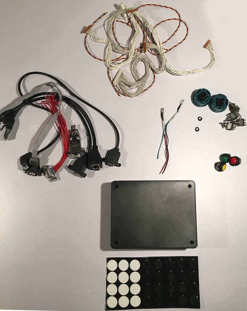
Initially, in order for you to make your own joystick, you would of course first collect all of the parts such as the joystick, buttons, wood, and finally the controller. When we first went down this adventure, we bought an I-PAC controller which had great software and did the job perfectly, but unfortunately was almost $40(USD) in price! While it was great to get a controller that served as a near-zero delay system that I could hook up to my PC. I decided to look for cheaper alternatives out there. Initially, we thought it would be awesome to load some virtual joystick software on a USB-compliant Arduino. It turns out that China has beat us to the punch on this one. 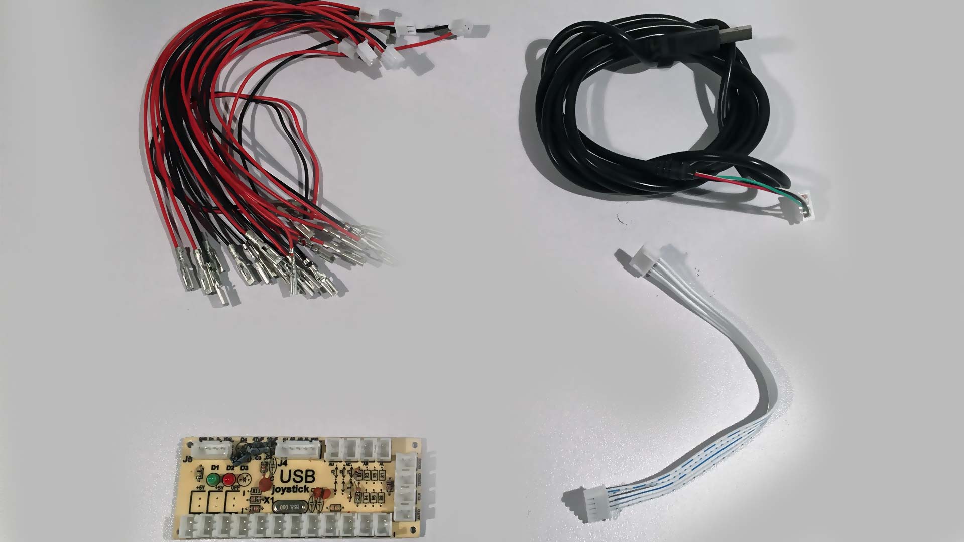 For this blog, we purchased the 7$(USD) kit as it came from an American vendor on Ebay. It came with the following items:
- The encoder board.
- a USB male A cable to 4-pin Molex connector
- 10x red and black joystick/button connectors
- 1x joystick connector.
Notes on the 3rd party knock-off Chinese joystick and buttons.
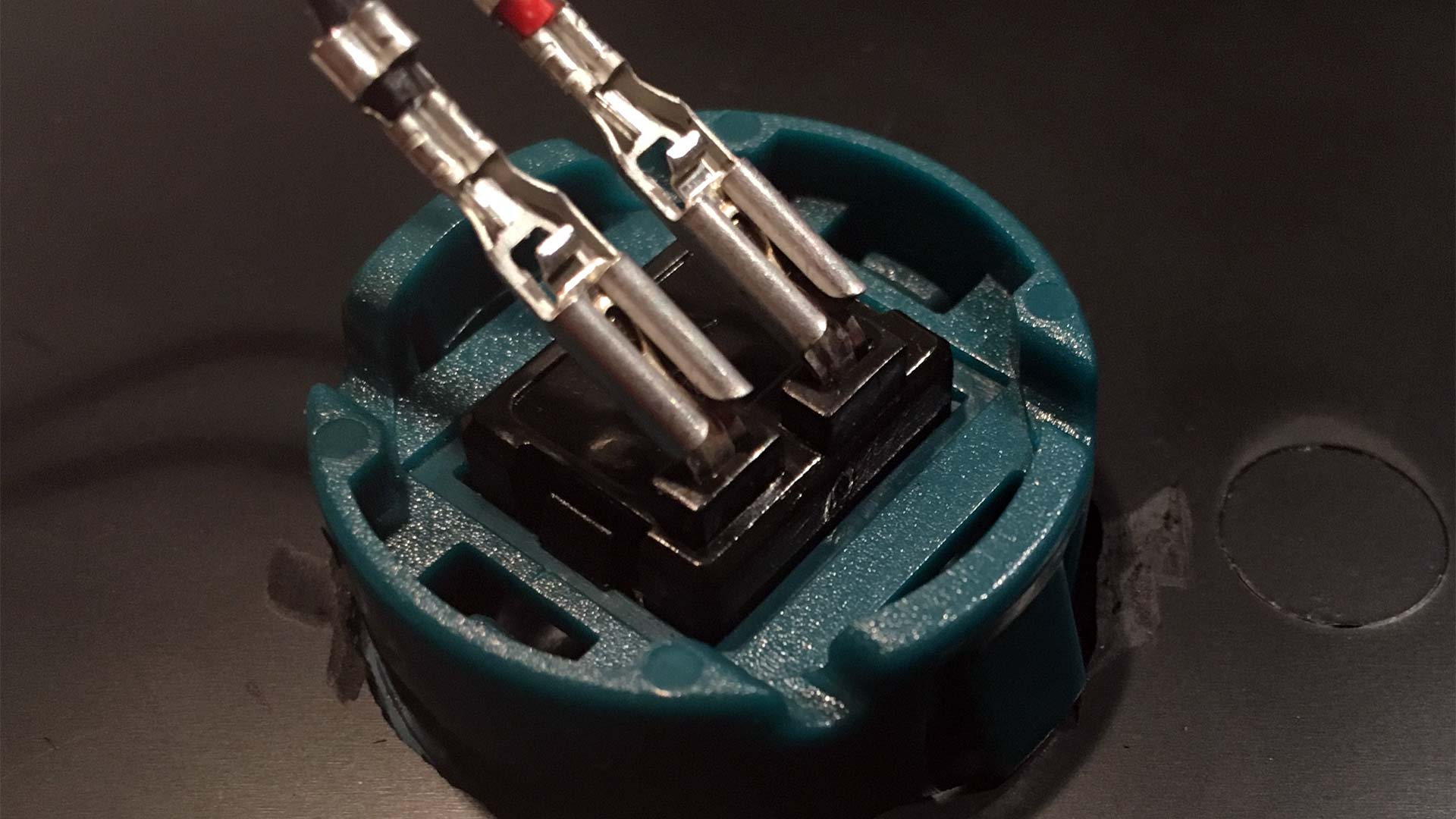
Usually, when you search for the zero delay controllers, they will be paired up with a joystick set that you will normally see below. 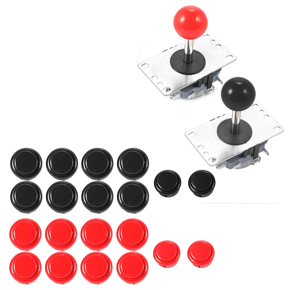
Picture above: A 2-pack of knock-off china buttons and joysticks.
The wiring harness is only compatible with the buttons and joysticks that China provides (but that does not stop anyone with a soldering iron!) These buttons and joysticks are not quality by any stretch of the imagination! (We're also including the knock-off HAPP products in this too. Yes, we're very much aware there are HAPP products that are knock-offs too).
When you see these types of buttons appear on eBay/Alibaba, They'll describe themselves as name-brand buttons. But are in fact knock-off Sanwa buttons. Complete sets typically sell anywhere from $14(USD) to $28 (USD). Compare that to a Suzo/HAPP/Seimitsu kit, and you could pay that much for the joystick alone!
It should also be noted that due to the nature of these being China knock-offs of legit joystick controllers. They may also come in under different names. Are knock-off buttons and sticks bad? Depends! If this is your first time building a fight stick and you're not really sure about your investment. Then go nuts. But if you really love arcades and fighting games. You might want to go for the real thing.
The quality of such third-party knock-off controllers is overall lacking, which is why I only bought a handful of switches for my project. Although they are cheap feeling the major advantage of these buttons is that they are very shallow, allowing us to easily fit them into project box cases like the ones we tend to use.
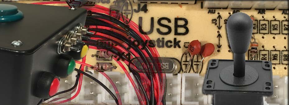
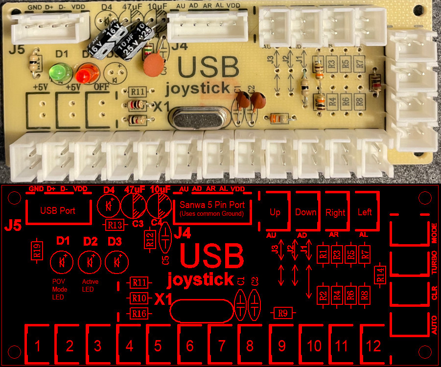
The joystick encoder board.
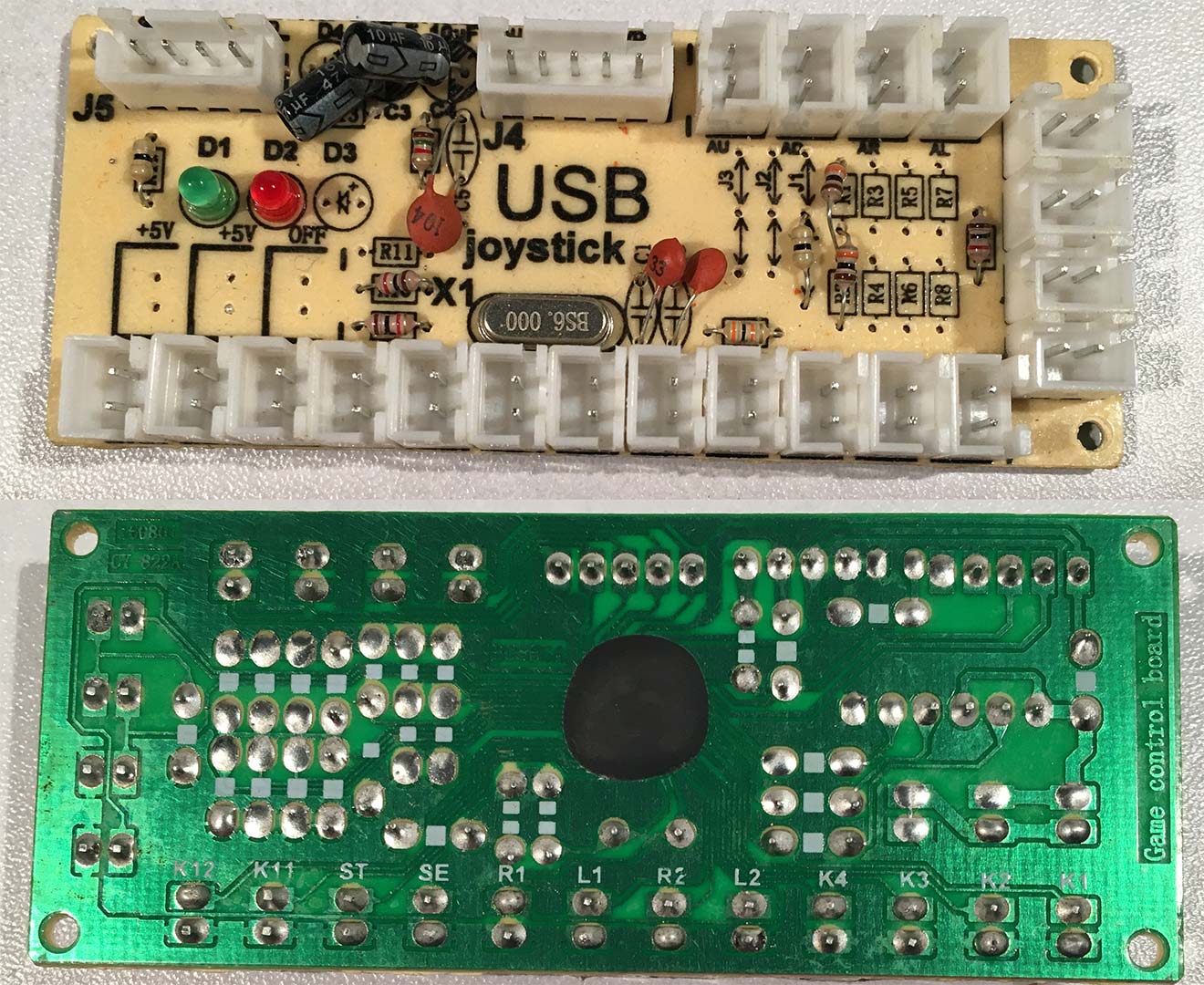
When you look at the board itself, there isn't really a whole lot going on. Initially, these boards came with a PS2 connector. Thus, why the button layout will be similar to that of a PS2 controller with R1, L1, R2, L2, etc. But there isn't a whole lot going on here because China threw some electrical epoxy onto the chip. The big thing we wish to point out to you is the mind where the traces are. Notice how, on the bottom of the board, all of the traces are connected together? That's ground.
PSX/PS1/PS2 version.
What do you mean "Initially these boards came with a PS2 connector?" I want to hook one of these bad boys up to my PS1/PS2!
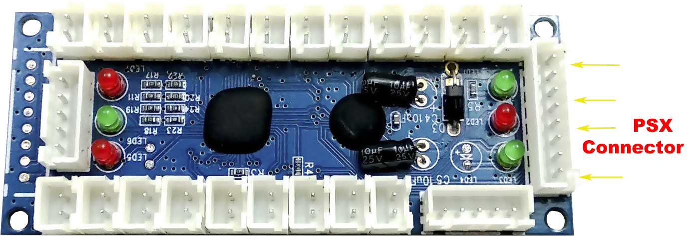
Although not as abundant or cheap as the Zero Delay Encoder used in this blog, they are still available. If you type in "Zero Delay Encoder PS2" into eBay, you should get results for a handful of these controllers. Please keep in mind that because half of the eBay community does not even know what they are selling, you will have to look out if the board you are purchasing has the PSX Connector pictured above. Ideally, the vendor should be able to sell you the male PSX wiring harness to go along with it. Prices on these boards can range from $12(USD) to $30(USD) depending on how complete of a kit you want to choose.
Special notes about the wiring.
 Zero Delay Joystick Adapter from the backside. Picture compliments of one of our readers, Chris. Thank you so much!
Thanks to a kind reader for straightening this all out for us. We used to think that the Chinese inverted the wires on it, as we thought that ground was what is going all around the board. It turns out, after verifying the traces ourselves, that actually 5vdc is going around the entire plane of the motherboard. So the Chinese were technically right about their wiring. Meaning that if you were to wire all of the buttons into an adapter, then you should daisy chain the red leads! Not black!
From an electrical design standpoint, it's still wrong! You should not have voltage running on a thick trace that would normally be a ground plane. Because now you have to take some extra care with this board if you intend to solder this bad boy down to something. You don't want any screws or washers to dig in, or else 'POOF'. Thus, the correct terminology we should be using is "COMMON"; 5 VDC is classified as common. And thus, it's standard wiring practice to daisy chain the common line around your sticks and go out to one single port.
Extra parts and tools:
The amount of parts you may use will totally be up to you and what you want out of your joystick encoder. Here's a list of my parts.
- Hammond style ABS plastic box
- 4x rubber feet
- 2x "Knock-off China" SPST buttons for "start" and "Select."
- 2x panel mounted RJ-45 female connectors
- 1x panel mounted USB "B" Style connector
- 1x DB15 female connector.
- 1x DB9 male connector.
- 4x SPDT switches (extracted from old cash register drawers)
- 3x small SPST buttons (used for the function mode buttons)
- 2x LED's with holders so we can mount the LEDs to the outside of the case.
- Big pile "O" wire!
Alternative parts:
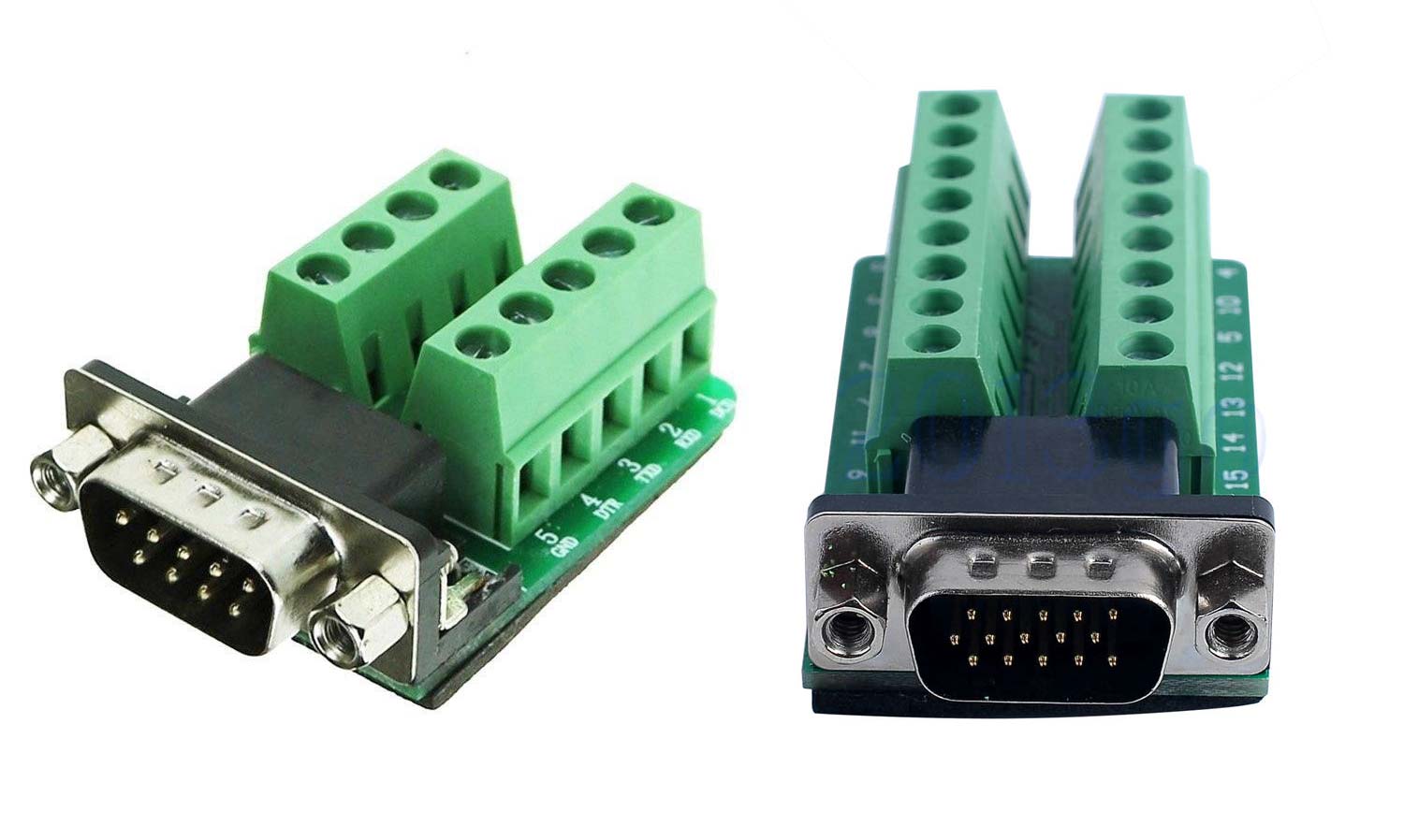
For those who are totally not feeling the soldering part of this blog. You can pick up what are known as "Terminal breakout connector," And they come in a variety of types and sizes. What is pictured above is male DB9 and DB15, but you can get them in both male and female components. These are super handy because if you mess up a wiring configuration, you can simply rip them out and start over with a simple flathead screwdriver. The downside of these is they are a little more expensive than just getting a header, which you could get for free out of an old computer screw or almost nothing from your local electronics store. Simply clip the alligator clips off with your cutter/plyers and slide them into the breakout connector. Use a flathead screwdriver to tighten the wires in place. done! The C=64 / Amiga / Atari joysticks are expecting a DB9 male at the base. The Cobalt Flux DDR pad is expecting a DB15 female at the base.
Tools:
- Soldering Iron
- Small screwdrivers to lock the panel mounts into the ABS plastic and for tapping screws on the top cover of the case.
- Dremel/Rotary tool with drill bit for carving out our holes in the ABS plastic
- Files for smoothing out edges and for making the square edges a little cleaner.
- Continuity tester - For actually making sure that you are connecting to the right pins on all sides.
- Pliers and/or wire strippers for soldering all of the connectors in.
Explanation of parts for our joystick encoder.
We wanted something that can test our C=64 and hook my Cobalt Flux DDR pads to right away, similar to our v1 box I did with the I-PAC controller. But also be able to hook up RJ-45s like my version 2 I-PAC box. Unlike the I-PAC, which maps to a keyboard, this encoder board maps to a joystick.
Hardware switchable input.
If anyone has ever tried the Xbox 360 Dance Dance Revolution pad on their PC. You'll know this problem very well, where if you step and hold pads in the opposite direction, the D-Pad only registers one direction. By adding 4 single-pull switches into the mix we can redirect the direction pads to buttons, allowing this joystick encoder to be used in situations like DDR/Stepmania, holding all 4-6 buttons if we really wanted to.
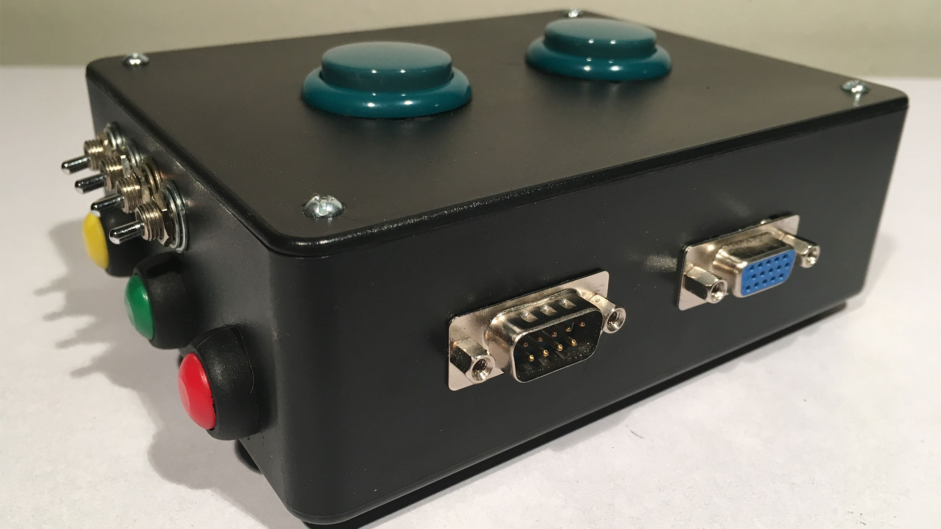
Assembly of our joystick encoder.
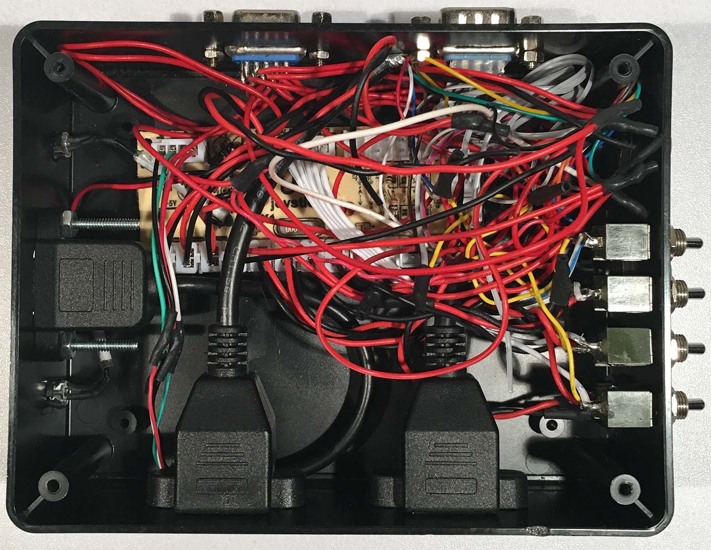 This is one of my not-so-proud moments in cable management.
But it was totally unavoidable given that you have wires coming in from four different ports and the switches as well diverting direction pads to shoulder buttons of this controller. But it actually assembled very well. You'll also note that the USB Type-B connector has the wrong wiring color for everything and had to do a continuity test on that as well before plugging it into the PC. Finally, the board itself is held down by Velcro as it doesn't need much to remain seated and stable inside of the confines of this box. The small LEDs were de-soldered off of the board, allowing larger ones to be routed to the outer half of this case. The LED clamps allow for easy removal in case we ever have to eject this board.
Installing the joystick encoder board.
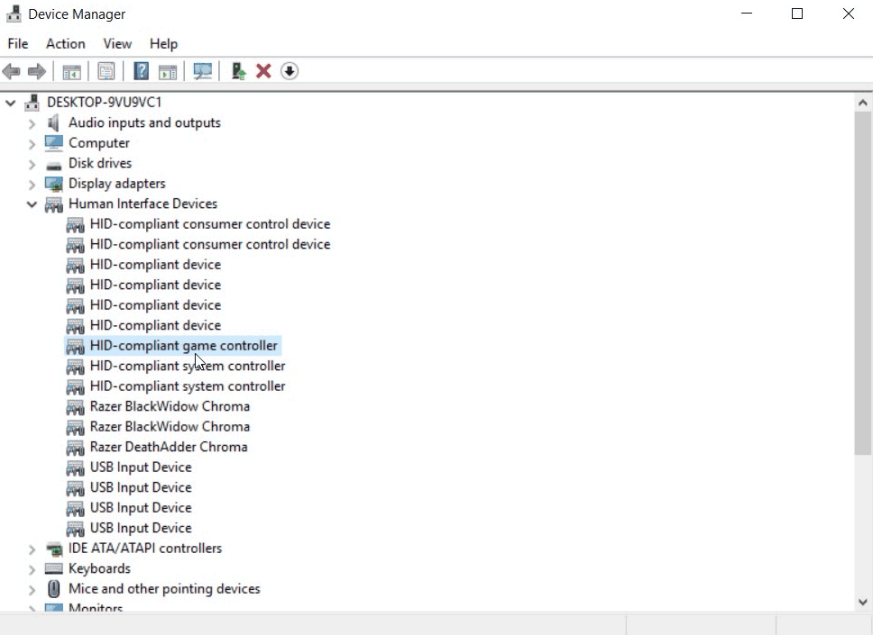
This is by far the greatest feature of this little board: the moment you hook it up to your PC, or Raspberry Pi, or even Mac, it finds drivers for a generic joystick, and that's it!
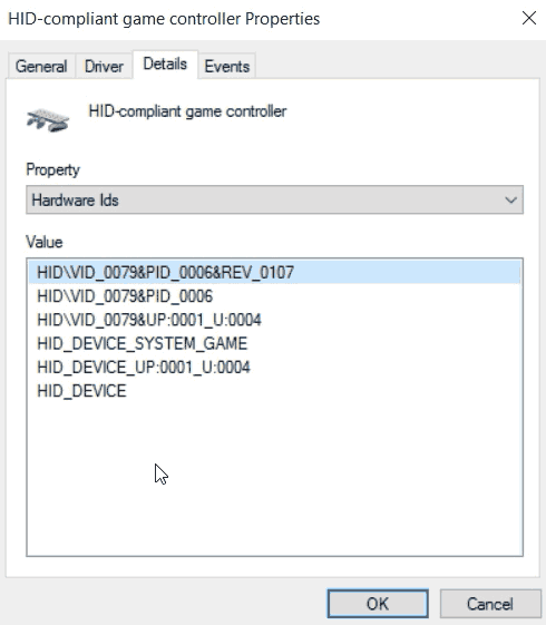
Pulling up the Hardware ID gives a VID_0079&PID_0006, which, simply put, is a Generic USB Controller device ID that has existed from windows 95 all the way to today with Windows 10.
Verification of joystick functionality.
To pull up the window above. You can press the Windows key + R to bring up a run prompt and type in:
joy.cpl
Then click on the Properties button.
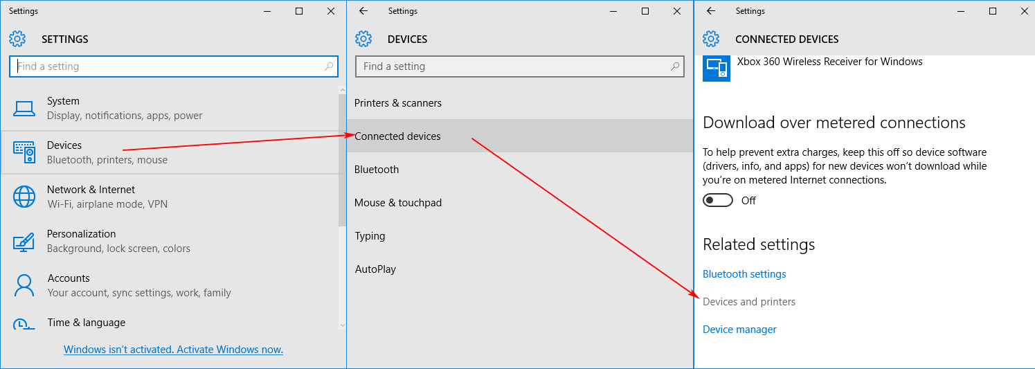
Alternatively, you can click on your Windows logo and click on Settings, Devices, Connected Devices, and scroll down to Devices and printers.
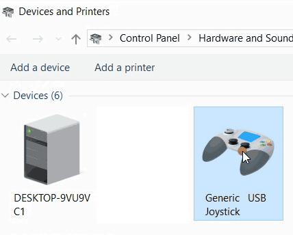
Right-Click the Generic USB Joystick in Devices and Printers and click on Properties.
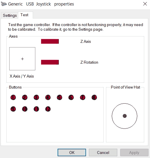
From here, you can take a flathead screwdriver and touch the ground with one of the signal pins to activate a button. Or, Plug the wires into buttons and begin pressing them to start building your very own DIY joystick.
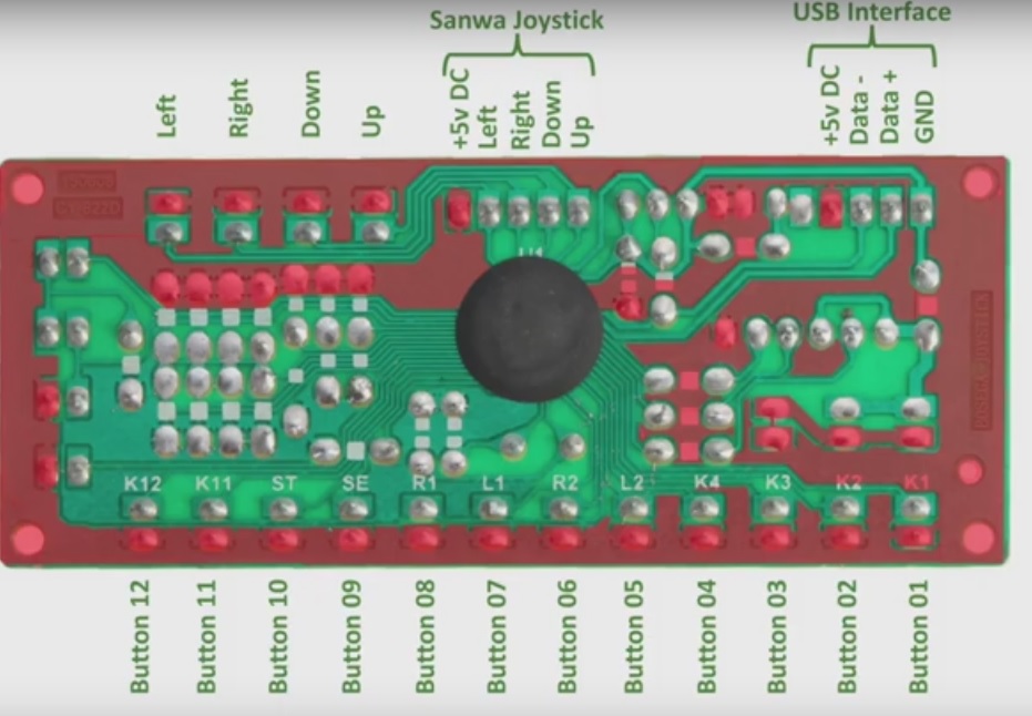
What are the Pinouts of the joystick encoder?!?:
We've included a video showing you the pin configuration layout that we are currently using to give just a few examples as to how you can use this zero-delay controller for your future projects. Now we shall break down the pins on the PCB, matching them to all of the connectors shown in the video for you to understand what is going on in our project box.
Excluding the USB Type-B connector. I'll try to break it down for you:
| Input | PS2 | RJ45 | DB15 | DB9 |
|---|---|---|---|---|
| 12 | Trigger 3 R | - | - | - |
| 11 | Trigger 3 L | - | Pin 10 | - |
| 10 | Select | RJ45 #2 Pin 7 | - | - |
| 09 | Start | RJ45 #2 Pin 6 | - | - |
| 08 | Trigger 1 R | RJ45 #2 Pin 5 | - | - |
| 07 | Trigger 1 L | RJ45 #2 Pin 4 | - | - |
| 06 | Trigger 2 R | RJ45 #2 Pin 3 | - | - |
| 05 | Trigger 2 L | RJ45 #2 Pin 2 | - | - |
| 04 | Square | RJ45 #2 Pin 1 | Pin 9 | - |
| 03 | Triangle | RJ45 #1 Pin 7 | Pin 8 | Pin 5 |
| 02 | Circle | RJ45 #1 Pin 6 | Pin 7 | Pin 9 |
| 01 | X button | RJ45 #1 Pin 5 | Pin 6 | Pin 6 |
| AD | D Arrow | RJ45 #1 Pin 4 | Pin 3 | Pin 2 |
| AU | U Arrow | RJ45 #1 Pin 3 | Pin 2 | Pin 1 |
| AL | L Arrow | RJ45 #1 Pin 2 | Pin 4 | Pin 3 |
| AR | R Arrow | RJ45 #1 Pin 1 | Pin 5 | Pin 4 |
| GND | GND | RJ45 #1 & #2 Pin 8 | Pin 1 | Pin 8 |
- Input - The input source written on the USB joystick encoder board.
- PS2 - What the button represents if it were hooked to a PS2 joystick. (Only relevant if your USB joystick encoder has the additional PS2 port on it.)
- RJ45 - This is a proprietary port set that we use for joysticks as it presents a cleaner approach to hooking joysticks up. See this blog article about the V2 stepmania pad.
- DB15 - This is for the Cobalt Flux version 2 dance pads. There are other dance pads which also use the DB15 connection system and you may have to make modifications.
- DB9 - This is our Atari/Commodore 64/Amiga Ports used for some really old joysticks. Keep in mind that the typical joystick only has one button thus additional modification may be necessary to get more buttons onto your old joystick.
Four switch DDR mode.
When the four switches are flipped up, the following keys are remapped:
| Input | PS2 | RJ45 | DB15 | DB9 |
|---|---|---|---|---|
| 8 | Trigger 1 R | RJ45 #1 Pin 4 | Pin 3 | Pin 2 |
| 7 | Trigger 1 L | RJ45 #1 Pin 3 | Pin 2 | Pin 1 |
| 6 | Trigger 2 R | RJ45 #1 Pin 2 | Pin 4 | Pin 3 |
| 5 | Trigger 2 L | RJ45 #1 Pin 1 | Pin 5 | Pin 4 |
Please note: With the zero delay controller, we are working in reverse polarity. Thus, GND is actually +5vdc. It's important to keep the trigger buttons clear so that when switching back and forth with the DDR pads, they do not interfere, especially if pin 10 is enabled for sessions such as "Pump it up" where diagonal pads are used, and the center is also counted as well. Also, switching the controls from directions on the joystick to buttons allows us to press all of the buttons on your DDR pad without any interference or extra software support such as XBCD/xb360ce needed with the Xbox 360 DDR pads. The reason why the Custom RJ45 connector goes to these pins is in the event we hook up a fighting stick, which will utilize many of the buttons this controller has to offer.
Final Thoughts:
This really should be considered as my "Version 3" DDR joystick encoder project as it cuts the cost of the controller board itself by 80 percent over the I-PAC controller. Outside of the bizarre fact that the voltage is going along the outside of the circuit, the only other thing I would probably add to this mod is some 0.1uf capacitors bridging between each connection and ground to at least attempt to fight static electricity that could happen when playing with dance mats on faster songs.
What we did is super overkill, and if you just want to set up this controller for a single function, such as a fighting stick or a DancePad, you will not have the scary wiring nightmare going on in our black box. The zero-delay joystick encoder certainly gets the job done, and it makes it exceptionally easy to add a joystick to any computer, be it a full PC, Raspberry Pi, and so on. For its super low cost, we couldn't even feel bad if it sets itself on fire. But for now it's working like a dream. You can find these on eBay super cheap too. We say that it's worth it.
Update 02/25/2019 - Humble pie time.
It has come to our attention that we may not have done our research on the arcade joystick and button world. To which we do apologize for that. Although we never claimed to be experts of anything! This blog only serves as a reference point for myself and others to follow along if they choose.
There are reputable vendors out there that will sell you HAPP, Semitsu, and Suzo-branded joysticks based on your preferences and tastes. If you find an error in what we say. Please! Leave it in the comments below. There's absolutely no reason to go into full-tilt nerd rage.
Update 06/08/2026 - two controllers act as one.
There was a bug that you could not hook up more than one Zero Delay controller to a PC because the driver was so generic that all of the controllers would act as just one controller. We suppose this would be true if we were talking Android OS and it took a generic keyboard .ky file. But we proceeded with testing in Windows.
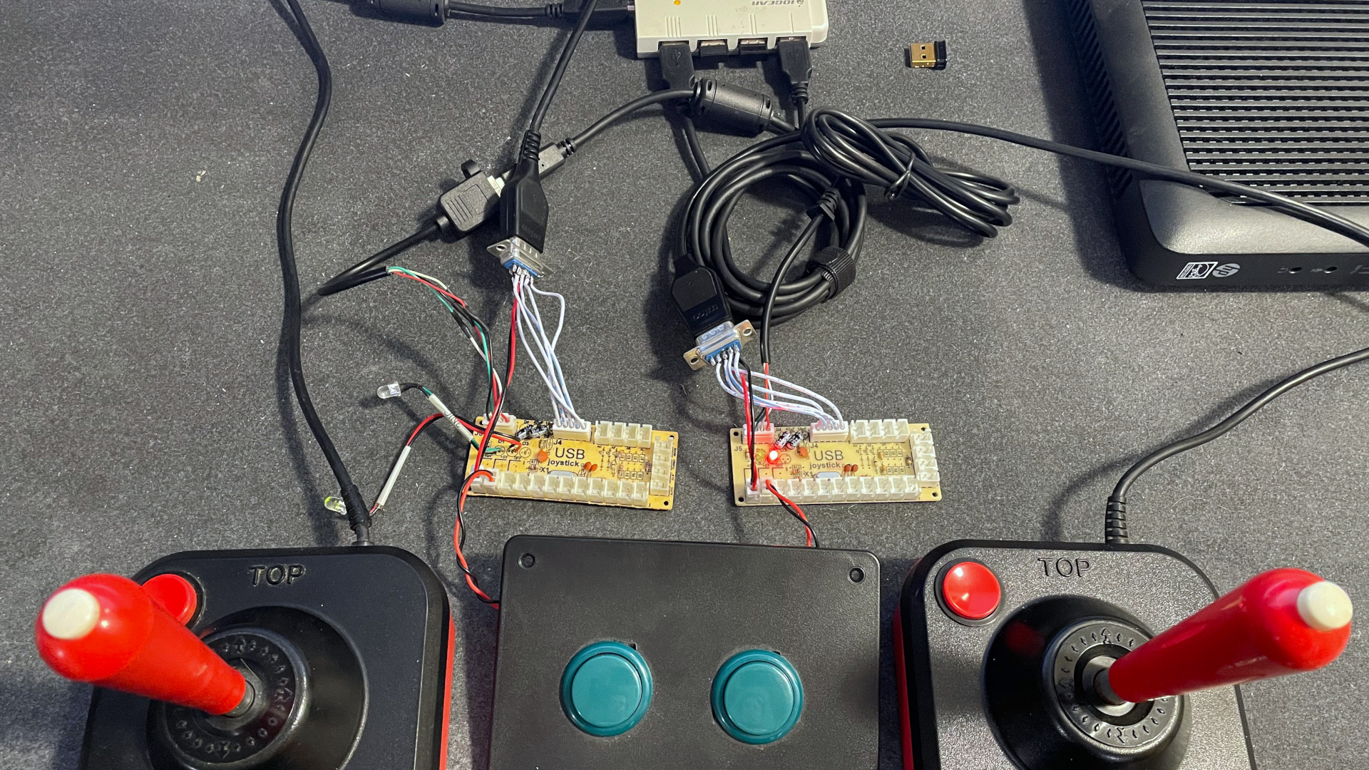
So in this picture we have our original Zero Delay Controller from this blog that we installed into a Hammond box on the left. And on the right we have our new Zero Delay Controller that we purchased from eBay for ANOTHER $7. We proceeded to hook up our classic Wico joysticks, and we use the buttons on the top of the Hammond as a secondary.
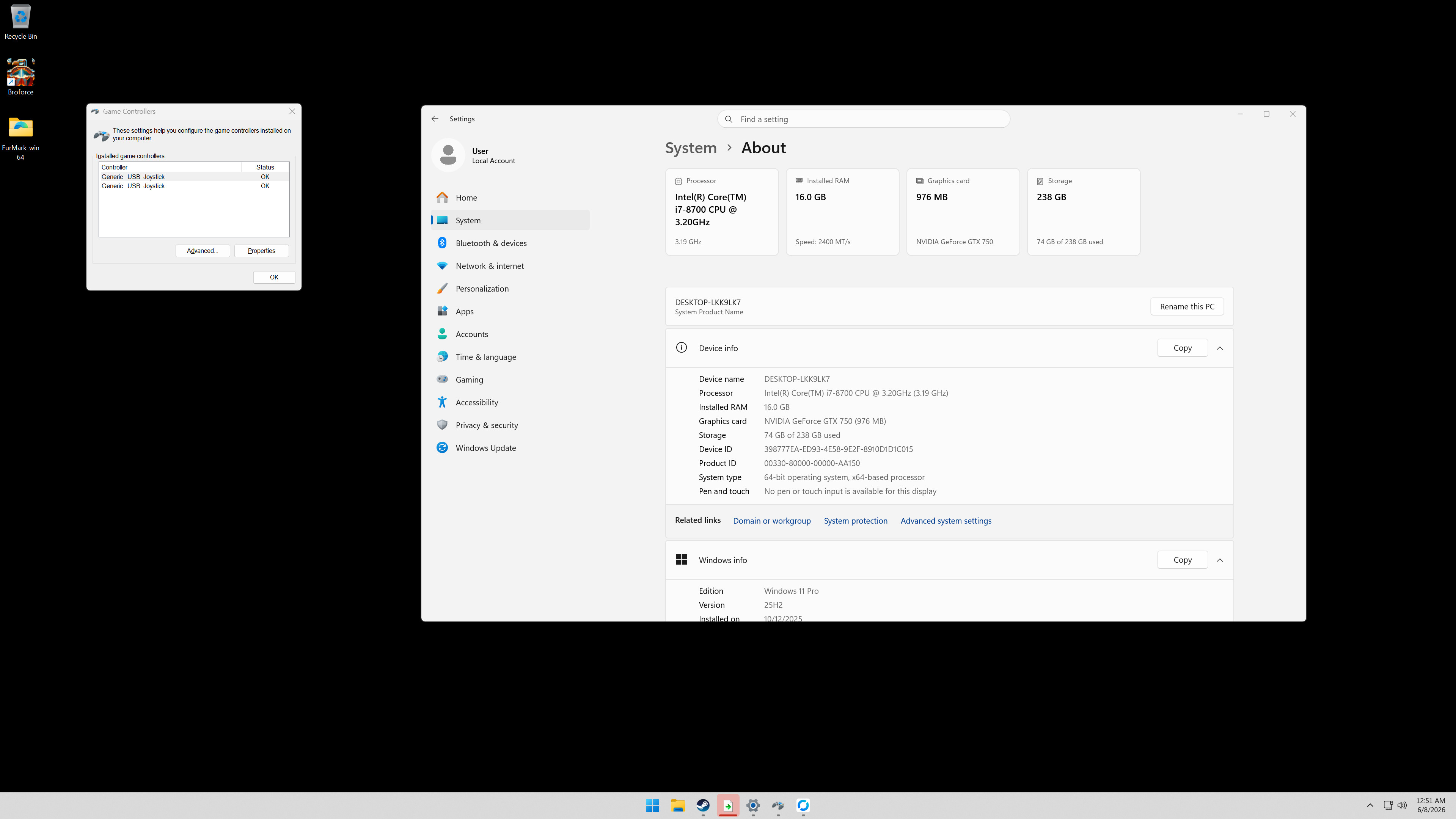
We're currently on the latest build of Windows 11 on our test machines, and joy.cpl is reporting that every function of our Zero Delay controller is available. Afterwards, we launched Steam and played Bro-Force, which, despite only having half of the buttons required for the game, we were able to control two separate characters after we were done.
So, if this was a problem in past operating systems. It does not appear in Windows 11, as we were unable to reproduce the problem that others had of all Zero Delay Controllers controlling player 1. Then again, the controller is so generic it might actually be an X-Input issue similar to the Xbox 360 controllers, where if you do not assign a player ID it defaults to 1. Bro Force can handle all XInput libraries, which allow you to bind keys, probably to each joystick.
That's all for the updates. Thanks for all of the feedback throughout the years. Until next time.
Server protects you.
END OF LINE+++
hello i am using multiple of these at once for a button box for a racing sim, however when i bind everything it all conflicts,
For example if i bind button 1 on board 1 button 1 on boards 2&3 do the same action
Hello,
Thanks for the input. This is serious as with DDR pads people tend to make two at a time for doubles and thus need two controllers to do so.
I will purchase another just to validate this error. It really should not happen as even if you plug in two identical joysticks windows should parse device based on a first plug first serve basis.
I will update this if i find the same issue you got going on.
Hi! Just wanted to know if you ever got around to checking this. I am looking into building a custom controller for DDR and would like to be able to use two pads at once.
Hello Jay,
We finally got around to checking this issue. After a bit of testing with a few early xinput games as well as with the xbox360ce driver for modern games. Also tested in Ubuntu as well as Windows 11.. We are simply unable to replicate the issue where both Zero Delay Controllers act as player 1. Even though the Zero Delay Controller is a very basic chip. Stepmania/Project Outfox should be able to see both controllers and map them accordingly as it uses a more classic X-Input driver library.
Hope that helps you out.
Also for doubles.. If you're just doing 4-way doubles. One Zero Delay Controller would be totally fine as there's 12 sockets for buttons. which gives room to spare for a start and select for both pads.
Anyhow, hope that helps.
- S