
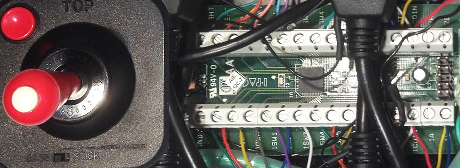
I-Pac controller in a new case with cleaner wiring.
When I first started this blog I created a posting about how I could build a better controller for Stepmania by using a device called an I-Pac. In the MAME community the I-Pac does what modern day mechanical keyboards do by assigning each key its own interrupt onto a micro-controller giving you the absolute fastest response between your joystick and your PC. The only way you could go any faster then this device is by bypassing the USB bus all together and wiring your controller via GPIO onto something like a Raspberry Pi.
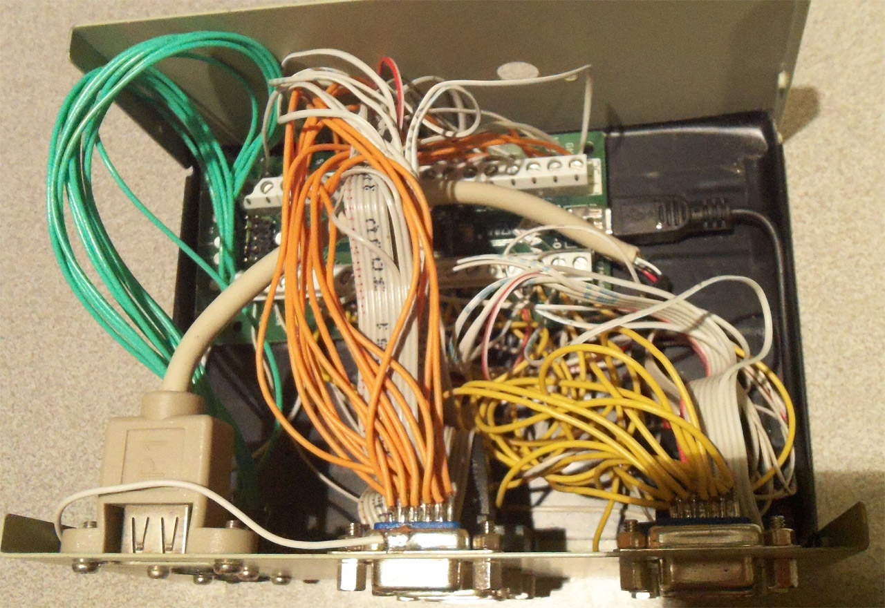 As you can see from the pictures above the wiring job that I performed was a total mess! But it was easy at the time. It gave me DB15 ports for my Cobalt Flux dance mats. and it gave me DB9 connectors for my old-skool joysticks like Atari's and Commodore based joysticks. I used a USB "A" port which is odd onto itself because "A" ports are supposed to be from source devices such as a computer.
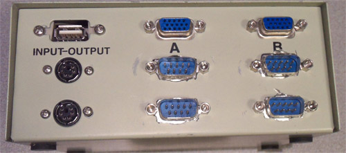
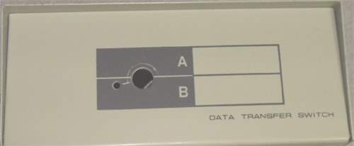 The box I used in my project was a KVM switch and with a dremmel I made the PS2 holes for the "A" and "B" ports bigger so that I could fit the DB9 connectors like I wanted. Hand rotary tools are great but they can often leave to some rough cutting. Top it off with an unsightly hole in the front and it requiring a new paint job. And even though everything works it didn't look pretty.
Until now!
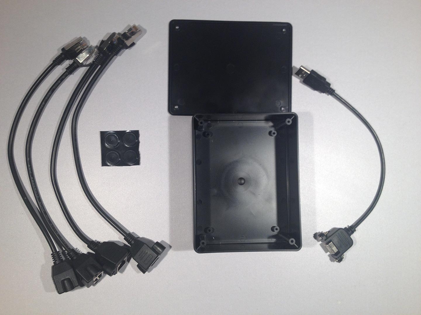 With purchasing about $15 bucks with of parts on eBay. We managed to acquire the following:
- project box at 45mm X 138mm X 106mm made of ABS plastic.
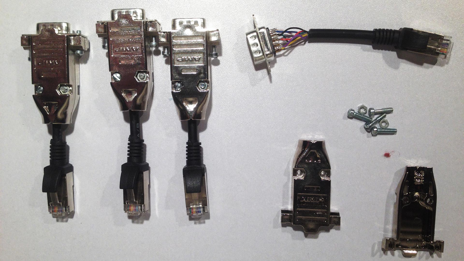
- qty 4 - screw-mounted RJ-45 extension cables which were approximately 150mm or 6inches each.
- qty 1 - Screw mounted USB "B" female connector to USB "A" male connector based extension cable also at 150mm or 6 inches.
- qty 4 - rubber feet (this item was free as I got these off of a Xerox printer warranty replacement.)
Fit test: Passed
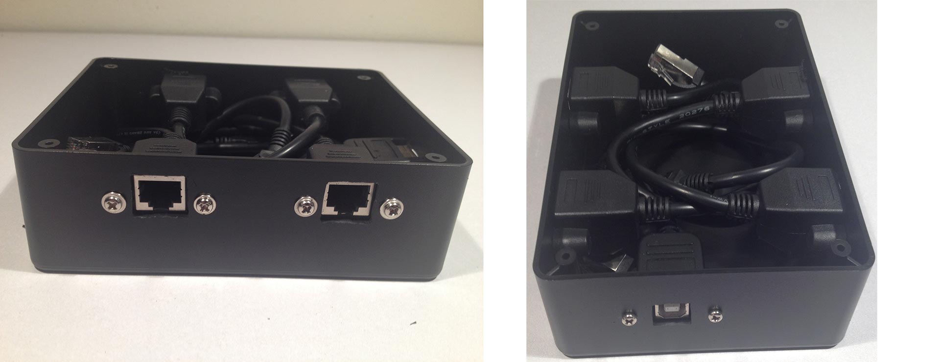
First thing is doing a fit-test. Just to see if all of the stuff purchased can fit into this small project box or if it was necessary to spend money on something bigger. Using my rotary tool with a small drill-bit making the pilot holes is so much easier than on metal. to make the ports nice and square a small file was used to fill out the corners. the RJ45 mounts did not come with screws but it was no big deal as old PC floppy drive screws worked rather nicely on the sides the box. As you can see, not only did we have room with the extensions but room for the board underneath. Excellent. 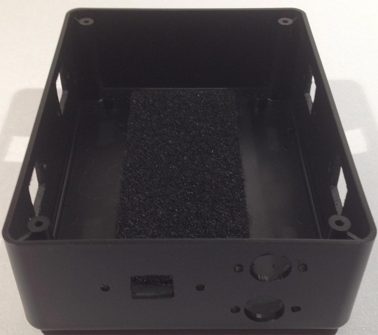 I continued to drill holes for the PS2 connectors. I placed them next to the USB port because when I first soldered the PS2 connectors from the old KVM switch onto the I-PAC ve controller there was actually a lot of slack in the wiring. I used this to my advantage and have all input jacks on just one side of the I-Pac controller box. Velcro is also applied at the bottom. It's not the most electrically sound thing to use velcro in this manner, but it keeps the board stable and allows me to eject the board if desired.
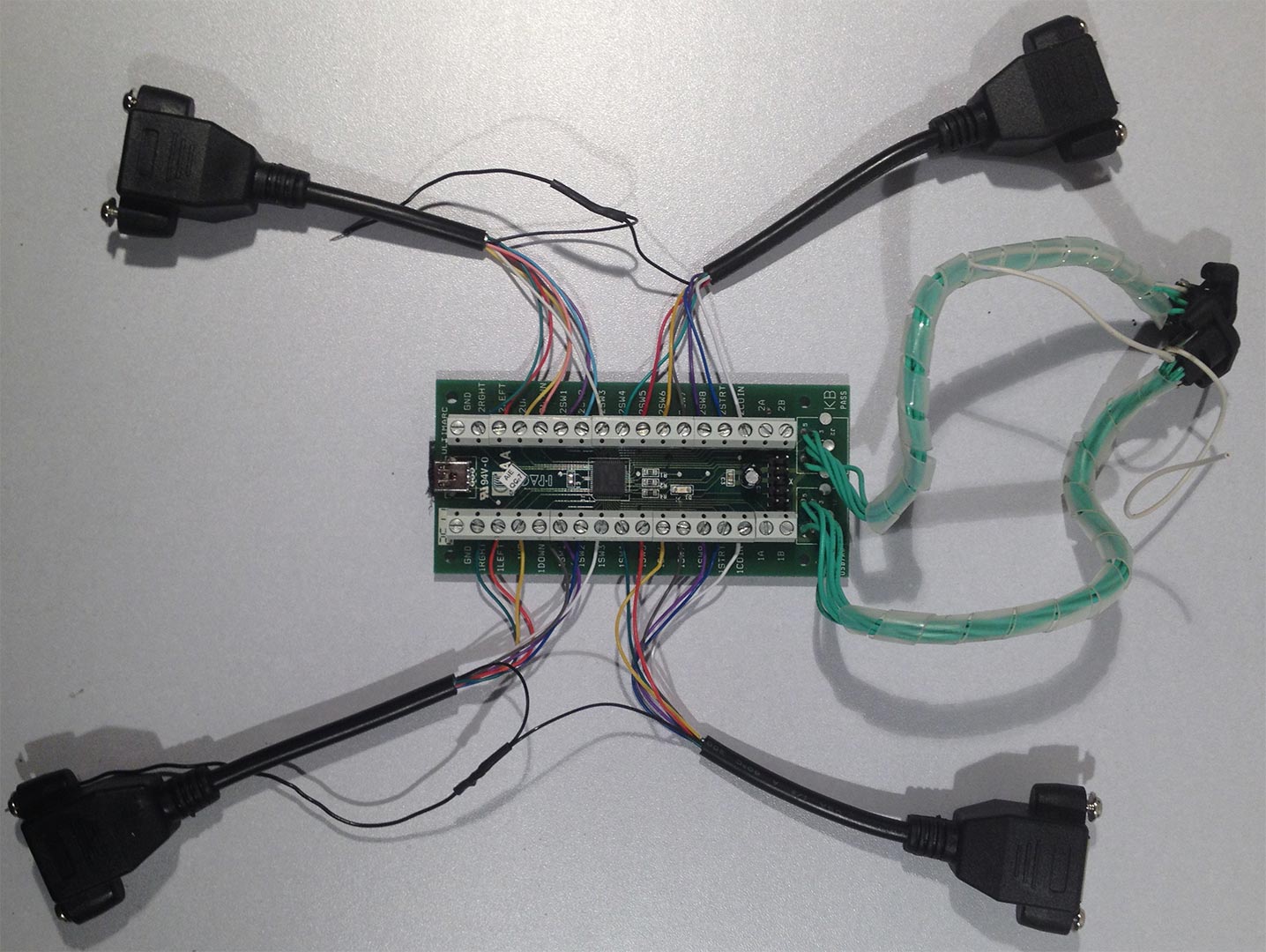
 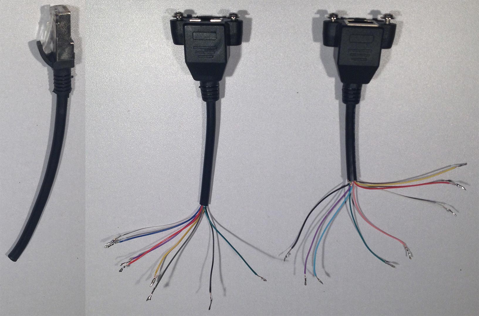 Next we start cutting up the RJ45 extension cables. We will want to get continuity on what each color is to help us assign where they go on the I-Pac controller.
| Pin Number | Color |
|---|---|
| N/C | Light Green. |
| 8 | Black |
| 7 | White |
| 6 | Cyan or Blue |
| 5 | Purple |
| 4 | pink or grey |
| 3 | Yellow |
| 2 | Red |
| 1 | Green |
It seems that my RJ-45 extenders came from two different factories and one of them used a 10 pin wire for RJ-55 serial connection. I saved the opposite end of the cable because there is something equally important that happens. It should be noted that this is just how the cables were received in our scenario. Wire coloration will change depending on make and/or manufacturer of the RJ-45 connectors so always do a continuity test with a volt-meter to ensure where all of your connections are going to.
Finally, save the other end of the RJ-45 male connector! We'll be using that near the end of the project.
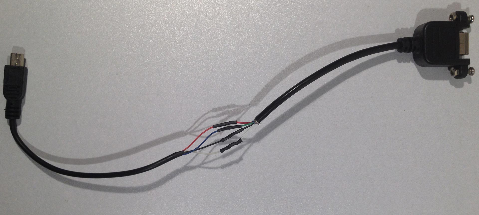
It was not possible to find a USB "B" connector to Mini "A" male connector on eBay. So I had to make it myself. Connections are very simple. Just follow the colors on the wires and you should be fine. The Mini "A" male connector was on the old project so it was simply transferred over. There is probably some older USB device in your house that uses the mini "A" style connector or if you purchased your I-pac you may have also purchased the cable to go with it. Later on, I had to take pliers to the insulation around the Mini "A" connector and strip that away in order to make it fit inside of the casing that was picked out.
I-Pac Controller wiring.
 Now comes the fun part about wiring this controllers up. Hooking everything up outside of the case is easier than bolting everything in to test with.
Everything works this way:
| I-Pac Input | Preset Key | RJ45 port & pin |
|---|---|---|
| 2B | Enter | Custom Green Button B |
| 2A | P | Custom Red Button B |
| 2Coin | 5 | RJ45 #4 Pin 7 |
| 2Start | 1 | RJ45 #4 Pin 6 |
| 2SW8 | V | RJ45 #4 Pin 5 |
| 2SW7 | C | RJ45 #4 Pin 4 |
| 2SW6 | X | RJ45 #4 Pin 3 |
| 2SW5 | Z | RJ45 #4 Pin 2 |
| 2SW4 | L-Shift | RJ45 #4 Pin 1 |
| 2SW3 | Space | RJ45 #3 Pin 7 |
| 2SW2 | L-Alt | RJ45 #3 Pin 6 |
| 2SW1 | L-Ctrl | RJ45 #3 Pin 5 |
| 2Down | D Arrow | RJ45 #3 Pin 4 |
| 2Up | U Arrow | RJ45 #3 Pin 3 |
| 2Left | L Arrow | RJ45 #3 Pin 2 |
| 2Right | R Arrow | RJ45 #3 Pin 1 |
| GND | GND | RJ45 #3 & #4 Pin 8 |
| 1B | Enter | Custom Green Button A |
| 1A | P | Custom Red Button A |
| 1Coin | 5 | RJ45 #2 Pin 7 |
| 1Start | 1 | RJ45 #2 Pin 6 |
| 1SW8 | V | RJ45 #2 Pin 5 |
| 1SW7 | C | RJ45 #2 Pin 4 |
| 1SW6 | X | RJ45 #2 Pin 3 |
| 1SW5 | Z | RJ45 #2 Pin 2 |
| 1SW4 | L-Shift | RJ45 #2 Pin 1 |
| 1SW3 | Space | RJ45 #1 Pin 7 |
| 1SW2 | L-Alt | RJ45 #1 Pin 6 |
| 1SW1 | L-Ctrl | RJ45 #1 Pin 5 |
| 1Down | D Arrow | RJ45 #1 Pin 4 |
| 1Up | U Arrow | RJ45 #1 Pin 3 |
| 1Left | L Arrow | RJ45 #1 Pin 2 |
| 1Right | R Arrow | RJ45 #1 Pin 1 |
| GND | GND | RJ45 #1 & #2 Pin 8 |
I kept the design of the RJ45 ports very simple because all of the wire twisting will be done on the other side be it a DB15 or DB9 jack. The reason why I choose pin 8 RJ45 as ground is that was the wire that is black so I kept the black wire to represent what it means.
Custom red and green buttons.
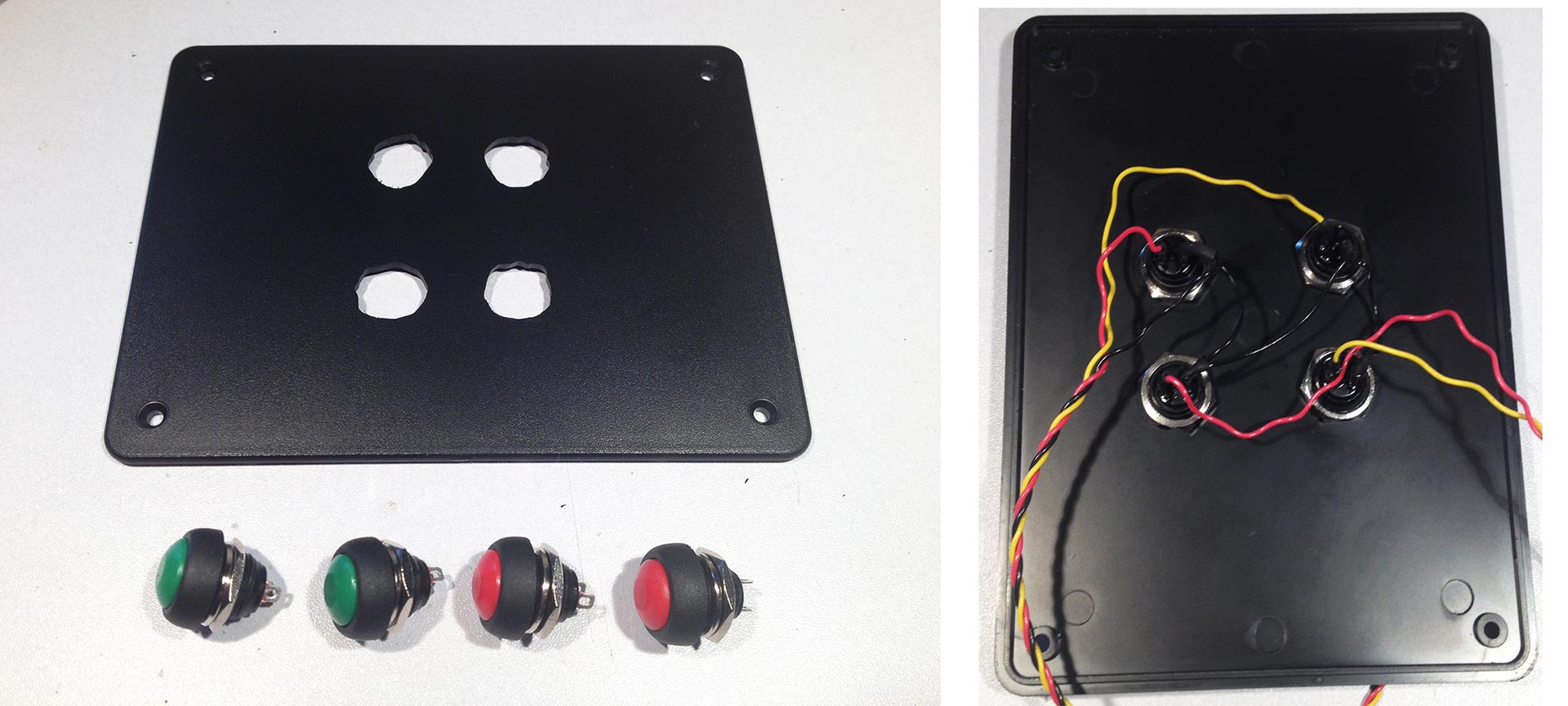 On controllers like the Cobalt Flux and other hard mats. The "Start" and "Select" and typically independent of the mat itself as you do not want to user pressing on the select key to back out in the middle of a Stepmania song. Typically those buttons are on the controller itself. This is a good design and will transfer that over. Minding where the RJ-45 ports were I was able to still have room to install these micro-switches on the top of the controller to act as those keys for both player 1 and player 2. The quality of the holes doesn't really matter as long as you don't make them too big where the buttons fall through. The moment you drop the washers in place the poor quality cutting will be hidden! Once it's all wired up with ground as the common just like the RJ-45 connectors we are good to go.
I-Pac controller assembly.
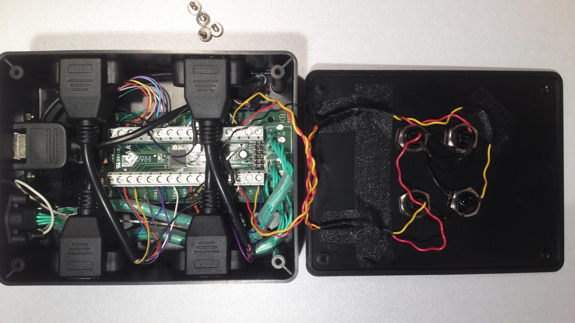 Finally we put it all together. With the proper measurement of everything all of the parts fit inside of the project box snug while still having access to all of the flat-head screws in case I needed to make modifications. The RJ-45 connectors were in a cross-cross wiring fashion for ease of cable management. and the board was offset a little to allow the PS2 cabling to get where it needs to go. Finally, I found some tapping screws that were used on a cheap PC case that involved you to tap the plastic headers of the case to secure the motherboard. These screws will be perfect for sealing up the I-Pac controller once complete.
Commodore, Atari and Amiga cable for I-Pac controller.
This is where the joy of keeping lots and lots of old cables come in. Harvesting a bunch of ancient serial cables that were hand-made I was able to get all of the parts needed to make a semi-professional looking set of converters to hook up to four DB-9 based joysticks for not only emulators but certain PC games such as Bub-N-Bros which is a Python-based supporting a lot of players for bubble bobble!
Pinouts are as follows:
| DB9 Pin Number | Action | RJ-45 Pin |
|---|---|---|
| 9 | Button 2 | 6 |
| 8 | GND | 8 |
| 7 | N/C | N/C |
| 6 | Button1 | 5 |
| 5 | Button3 | 7 |
| 4 | Right | 1 |
| 3 | Left | 2 |
| 2 | Back | 4 |
| 1 | Forward | 3 |
Pin 7 is not connected for safety reasons as older systems send 5vdc down this line. It may be a little dangerous to assign pin 5 as well as some systems use that as a 5vdc line as well. This only applies if you're making controllers that actually hook up to retro systems. If you are building a retro-joystick that hooks up to the I-Pac then you can assign up to 3 keys which is useful for games such as Jamestown.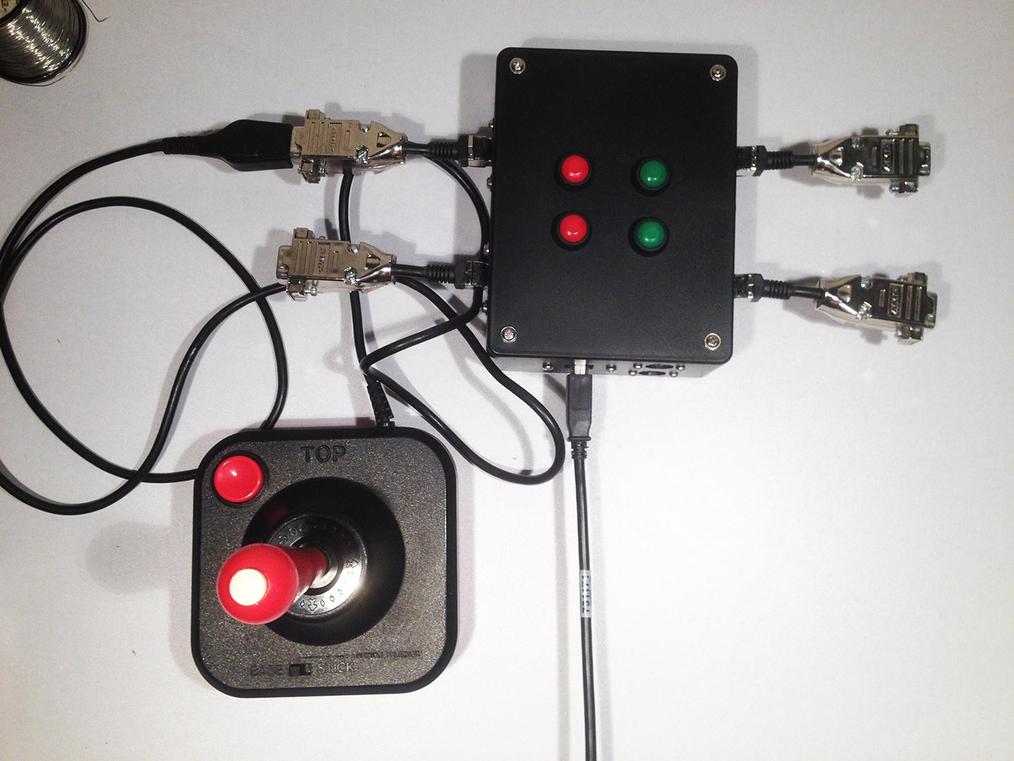
Finished I-Pac update: The End.
Final Thoughts.
With my trusty Wico jemstick I plugged it in and enjoy some old Commodore 64 titles in the way I used to enjoy them as a child. On top of this with the help of the I-Pac utility that comes with this board called WinIPac I found that two of my joysticks have shorts in them which is understandable given the age of my joysticks is pushing 20+ years!!! Thankfully, I saved a lot more serial cables which means rebuilding will be very easy. An ominous black box makes it look a little too much like a bomb! I should probably get some stickers on the thing explaining what it is and what ports go where. The only real thing that I still need to to this is to add LEDs. But I fear it might be as distracting as my Xbox receiver mod which is why i left it out. This completes the new case mod update. Hope you found it helpful. Server protect you. END OF LINE+++