
We tried to be professional about it making our own raspberry Pi Case. But that's lame. So you get to see us screw up and still win!
This is going to be more of a document and guide of our trials and errors in how we designed our Raspberry Pi 3 case. We did learn a lot about the general manufacturing process of trying to get one done professionally and even though we failed in some respects we are at least able to provide you better instructions than just making something, in theory, crossing our fingers and hoping for the best.
Why make a case?
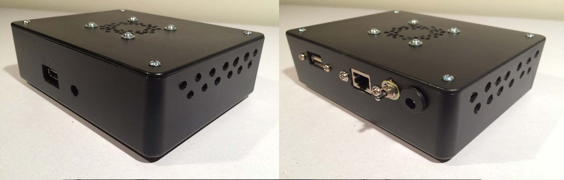 While we did have moderate success using hand tools and pre-fabricated ABS plastics with our Orange Pi. This was a great design. But well! The ominous black case with switches and plugs makes it look like a bomb. And even though the bomb aesthetic is sexy. We wanted something a little special for our Raspberry Pi 3. Now I know what some of you readers are thinking:
Just pay $7-$15 and BUY one! Sheesh!
China Pi Cases.
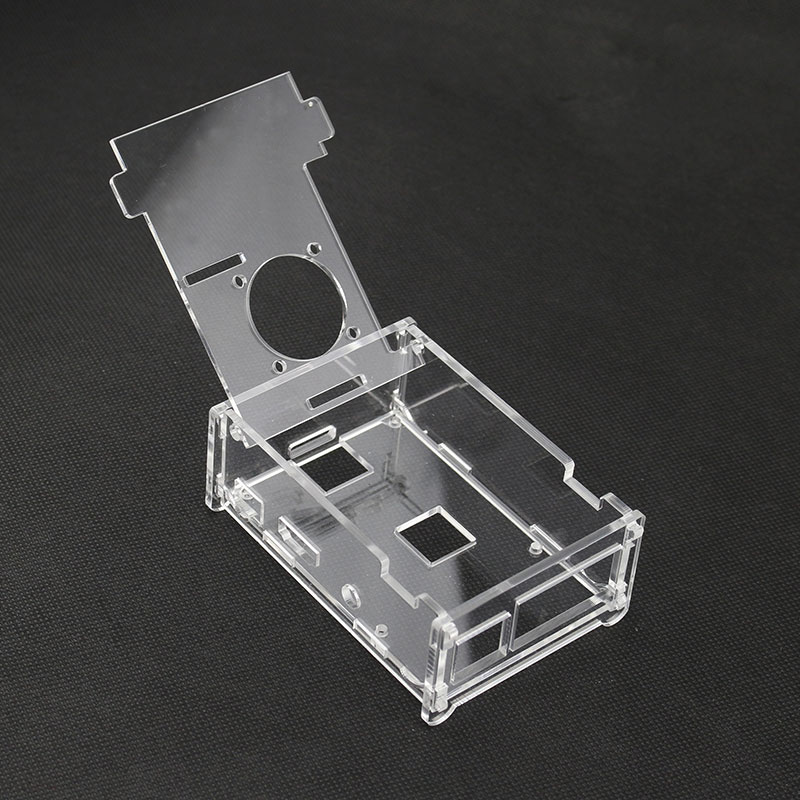 To which if I wanted a basic boy Raspberry Pi to quickly assemble and tear apart again then great. Yes, this piece of crap acrylic case that you buy from China will be just fine. But it doesn't fit my needs and here's why.
- Space - Everyone wants to go as small and thin as possible resulting in you choking your Pi.
- Clean - We attempt to go a little clean by not having slots all over the place for cameras, LCD, and so on. Perhaps it will suck down the road when we need to hook up a camera. But we'll cross that road when we need it.
- Stable - A lot of the shit cases out there rely on force-fitting the plastics together or side-mounting screws to give their rigidity. In some cases, the Pi board simply floats around inside which sucks.
Design.
So what is a lowly blogger like me going to do?!?! Design my own of course. I wanted a case that can handle DC-DC power conversion so I can just use a 12v Barrel Plug. As I explained in my previous blogs dealing with Pi's. A lot of problems with lock-ups stem from a terrible power supply and an even worse power cable. But having a DC-DC regulator this close to the Pi. There's no room for error. Also, 12v power supplies seem to be the most abundant thing we can find in the world so why not? 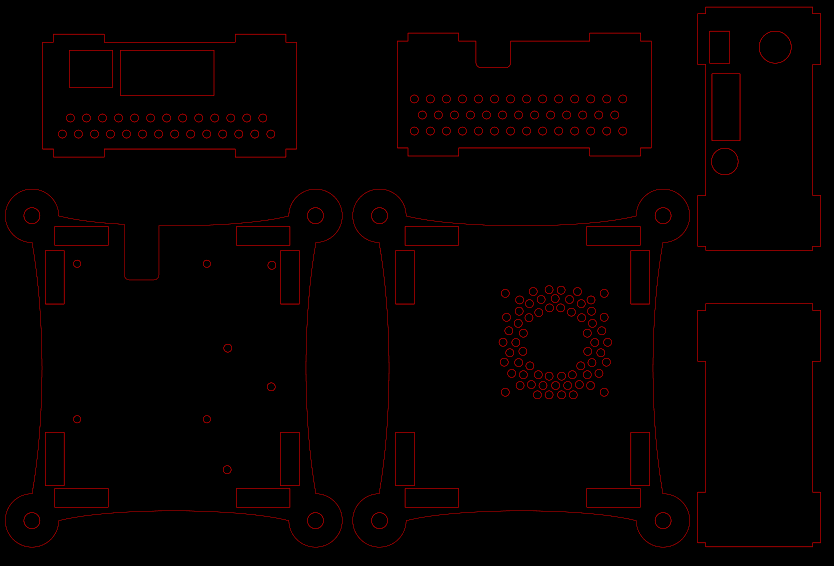
Download
![]() The best part of this all is you can download the schematics for the case I'm building to follow along. This was originally designed in Inkscape SVG. But we also saved it in PDF and Illustrator CS6 for those people that like throwing money into a fire pit. Simply click on the download link to receive the 7-Zip archive to follow along.
The best part of this all is you can download the schematics for the case I'm building to follow along. This was originally designed in Inkscape SVG. But we also saved it in PDF and Illustrator CS6 for those people that like throwing money into a fire pit. Simply click on the download link to receive the 7-Zip archive to follow along.
Creative Commons License.
![]() This file is under a Creative Common Attribution 4.0 license. Pretty much meaning Share it, mod it, do whatever the hell you want with it. The only thing I'd like is maybe some shout-outs. Simple huh?
This file is under a Creative Common Attribution 4.0 license. Pretty much meaning Share it, mod it, do whatever the hell you want with it. The only thing I'd like is maybe some shout-outs. Simple huh?
Always check the work.
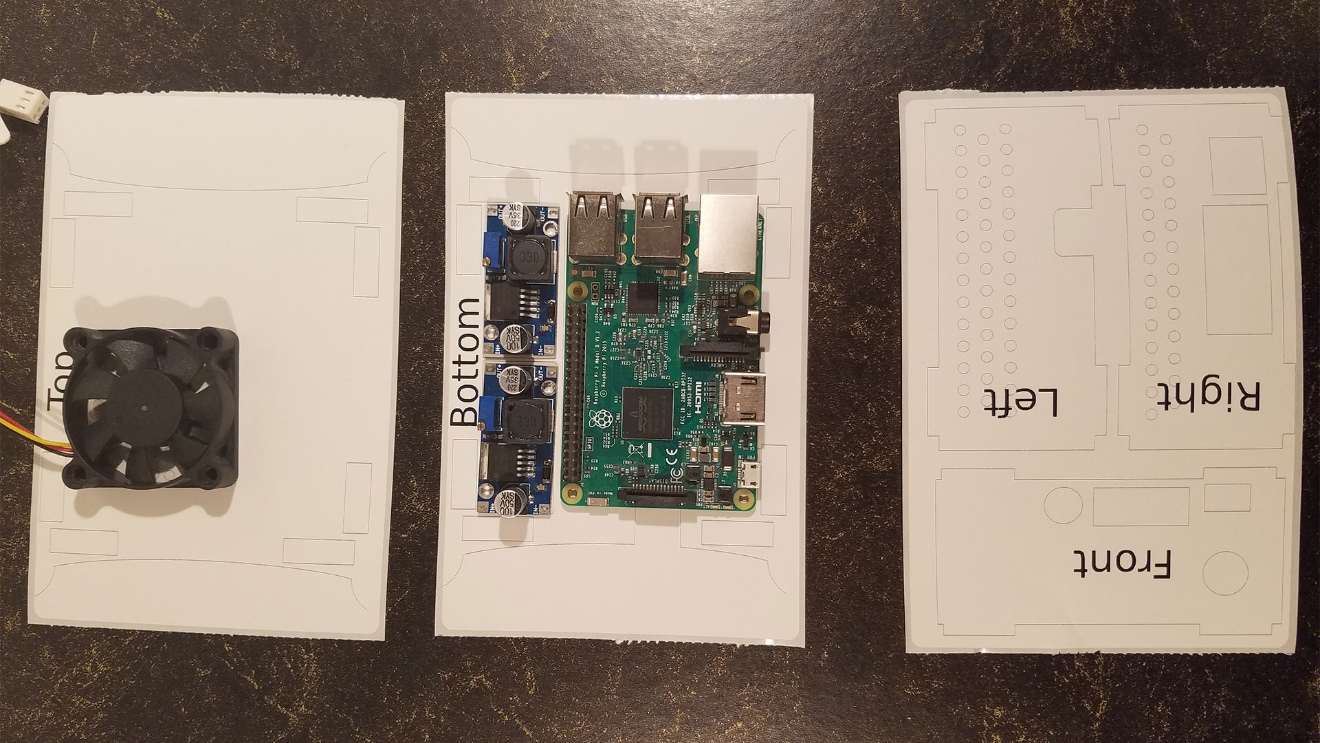 The number one thing that has always bitten me in the ass over the years is trusting other people's work. Especially the measurements of electronic devices. There are times where the vendor I'm dealing with cannot tell the difference between a 32mm part and a 12mm part. Just "It's the same. You buy now!" So on that note, I urge everyone to check the work by printing out my schematics on a sheet of legal paper and lining your hardware against it to make sure those screw holes are where they are supposed to be. Because I had a thermal printer I simply changed the paper size and moved the vector objects into the area for it to print. Paper costs less than polycarbonate or practically any other substrate. Use it to make sure your screw holes line up. and if the part dimensions fit into your case. Don't be an asshole like us and skip this step going immediately into production.
Professional Cases require special tools.
For this run Grandma let me use her ultra-expensive robotic router to perform this job. Why does she have a robotic router? Because Nanners needs to cut up the fruitcake for everyone and it's the only thing that can do the job. She goes half an inch per second at 30,000 RPM because anything faster through her delicious fruitcake and gives a motor stall error. For the material, I will be using 6mm polycarbonate plastic which is similar to the properties of Lexan, Perspex or Excelente. Why do you ask? It was in Grandma's backyard. She uses it for plating her spider plants. So she tells me. Polycarbonate plastic is completely overkill and expensive. But it won't crack or shatter like traditional acrylic.
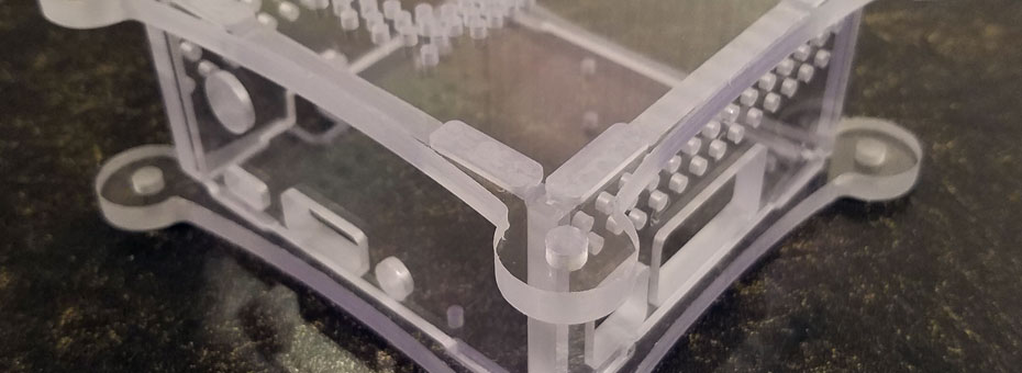
Robotic Routing Results
 Holy hell that looks rough!
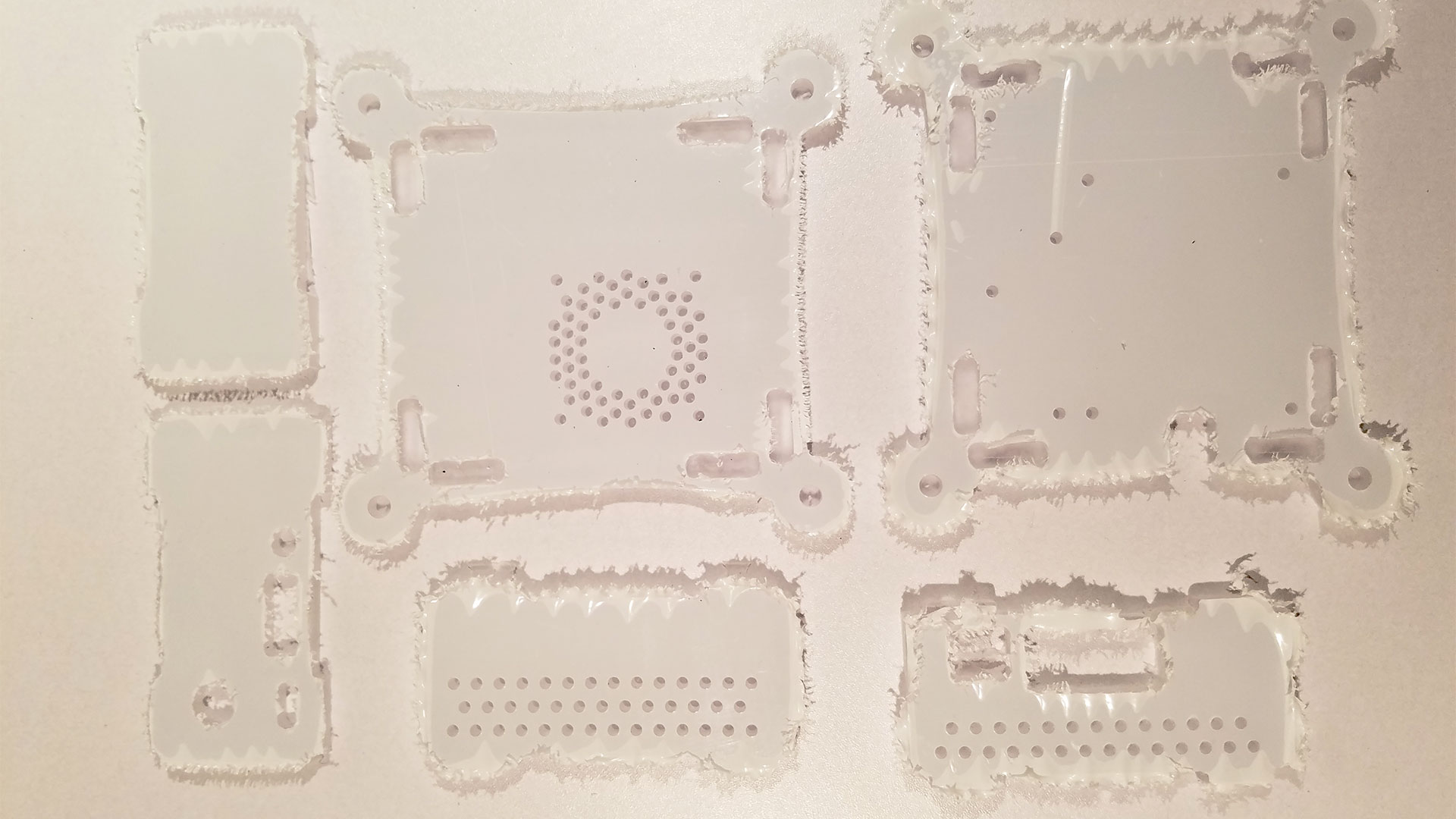
At first, you'll notice how horrid the cuts look. This is because we cut with the protective plastic on. Even though it is polycarbonate we were drilling a lot of holes for ventilation and do not want the sudden pressure of the drill bit to come down hard and start cracking into the neighboring holes. Having that thin coat of plastic on acrylic amazingly helps if you are drilling into it or using your rotary tool to cut into it. You can also use masking tape to emulate the same effect too. 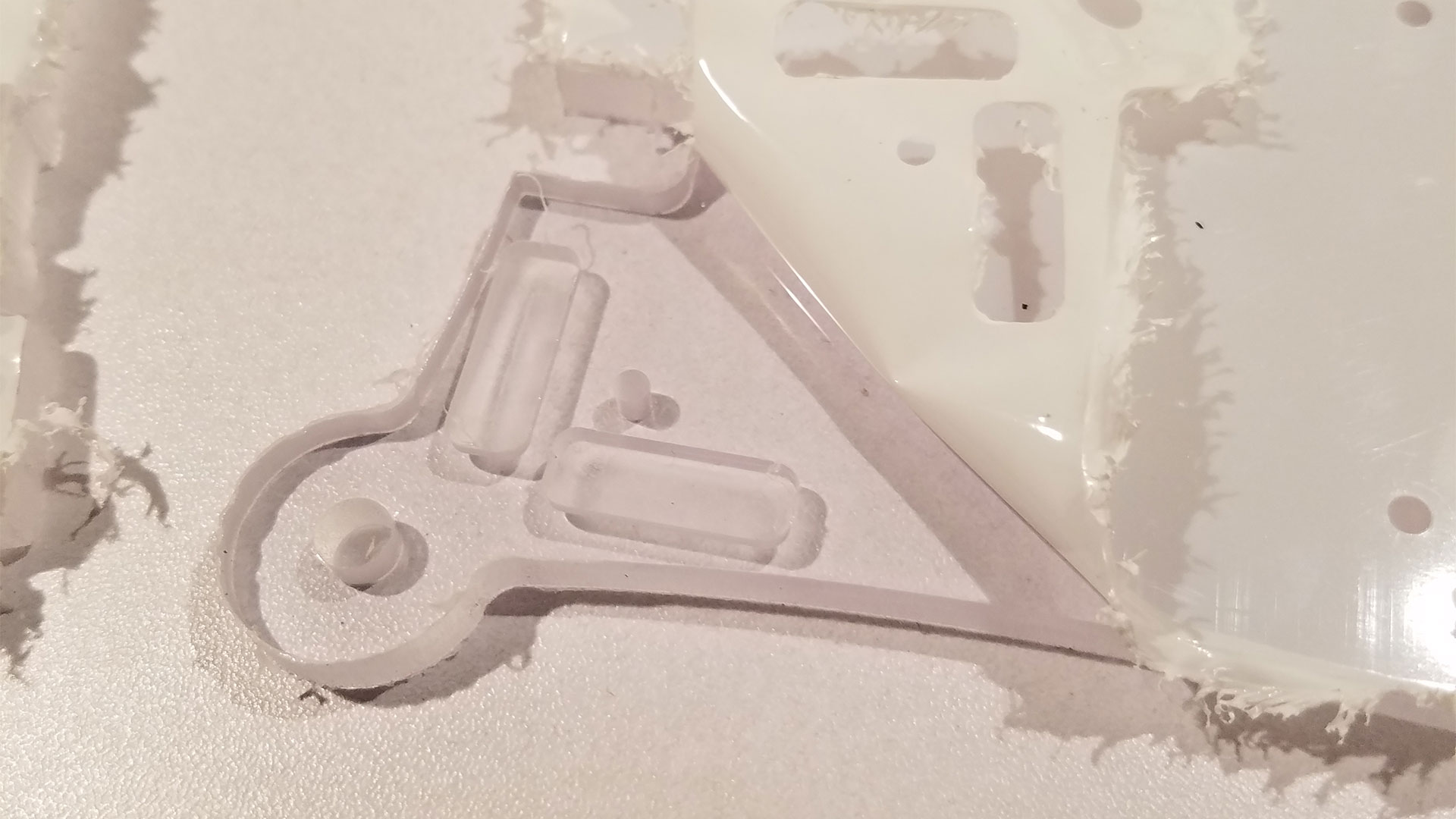 As you peel back the sticker you reveal the clean finished product along the inside. This is legitimately the only advantage a standard robotic router has over water and laser knives. The Ability to specify how deep the bit goes to engrave into your material. It's a great way to make the case feel clean looking but you have to watch the thickness of your notches which segways us right into! -
Routing defects.
 Those people with a laser or water knife will not have these problems. Since we were using a robotic router for the first time there were all kinds of errors on my parts as we were peeling away the protective sticker.
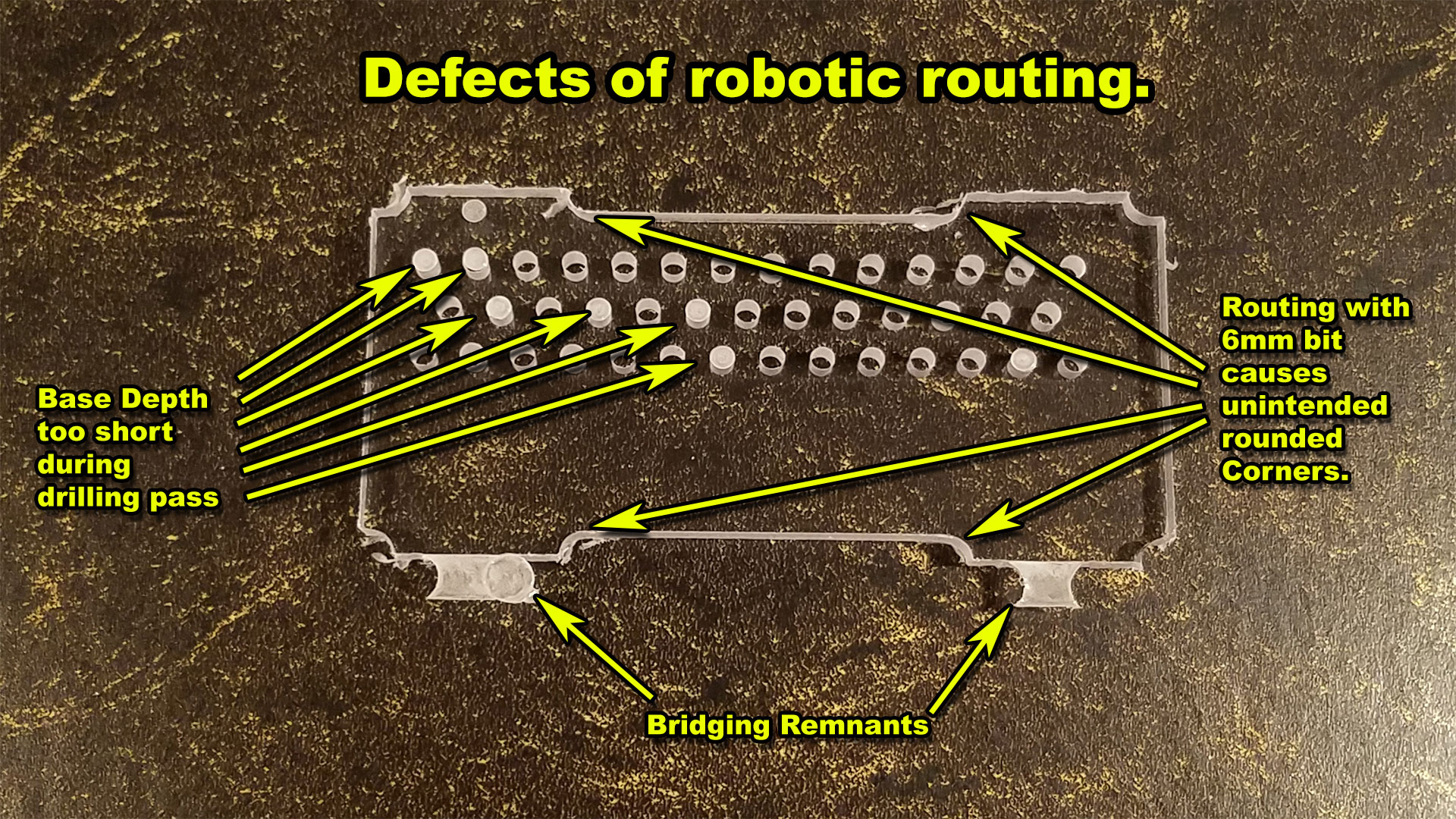
- Bridging Remnants - This defect is intentional and designed to keep your part on the bed as this routing bit is flying all over your part. These are small parts we're trying to route on a giant table. If I didn't bridge then they would get destroyed the moment the last bit of Polycarbon was routed away. Usually, the bridge depth is so thin that you can bend back and forth with your hand until it breaks free. But that requires additional sanding and flaming if it's pure acrylic like an Optix brand.
- Base Depth too short on drilling pass - In my paranoia of not wanting to drill through the table despite placing an underlay before starting the job. I set the base depth to 6mm which is the same as the material. The problem is that as the router bit drops into the material it flexes ever so slightly. Leaving these clogged holes. Now many of them I was able to poke out with a pen easily. some even fell out bypassing my fingers over it. A minor mistake is still a mistake.
- Routing with 6mm bits around corners - This is probably my biggest mistake about the project. I was alternating between 3mm and 6mm routing bits. Not thinking as it was cutting the 6mm bit is awesome for cutting the outer portion of the case. But there's a terrible downside to it all which is when you have to make interlocking acrylic
Inside corner route failure.
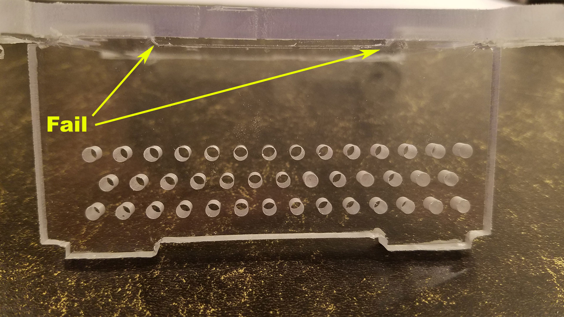 This combined with not engraving my holes to 3mm instead of 3.5mm or even 4mm creates this gap of failure in the plastics. That because the edges are rounded in these tight areas there would be no way for the part to sit flush where it should be. Now there are some solutions to correct this like I could use a router that has a 1mm bit that could break easily on plastics like this. But that would still make a small 0.5mm rounded corner! So ultimately I would have to tell the router to route about 3mm up into the materials. It would make a series of very small holes around each corner. But it would also act as relief points so the sides can sit flush like they are supposed to. These mistakes mean using hand tools like a rotary tool with a carbide disc. The quality isn't as awesome as if it came off of a robotic router. But it's still salvageable.
No vertical depth for SD card extraction.
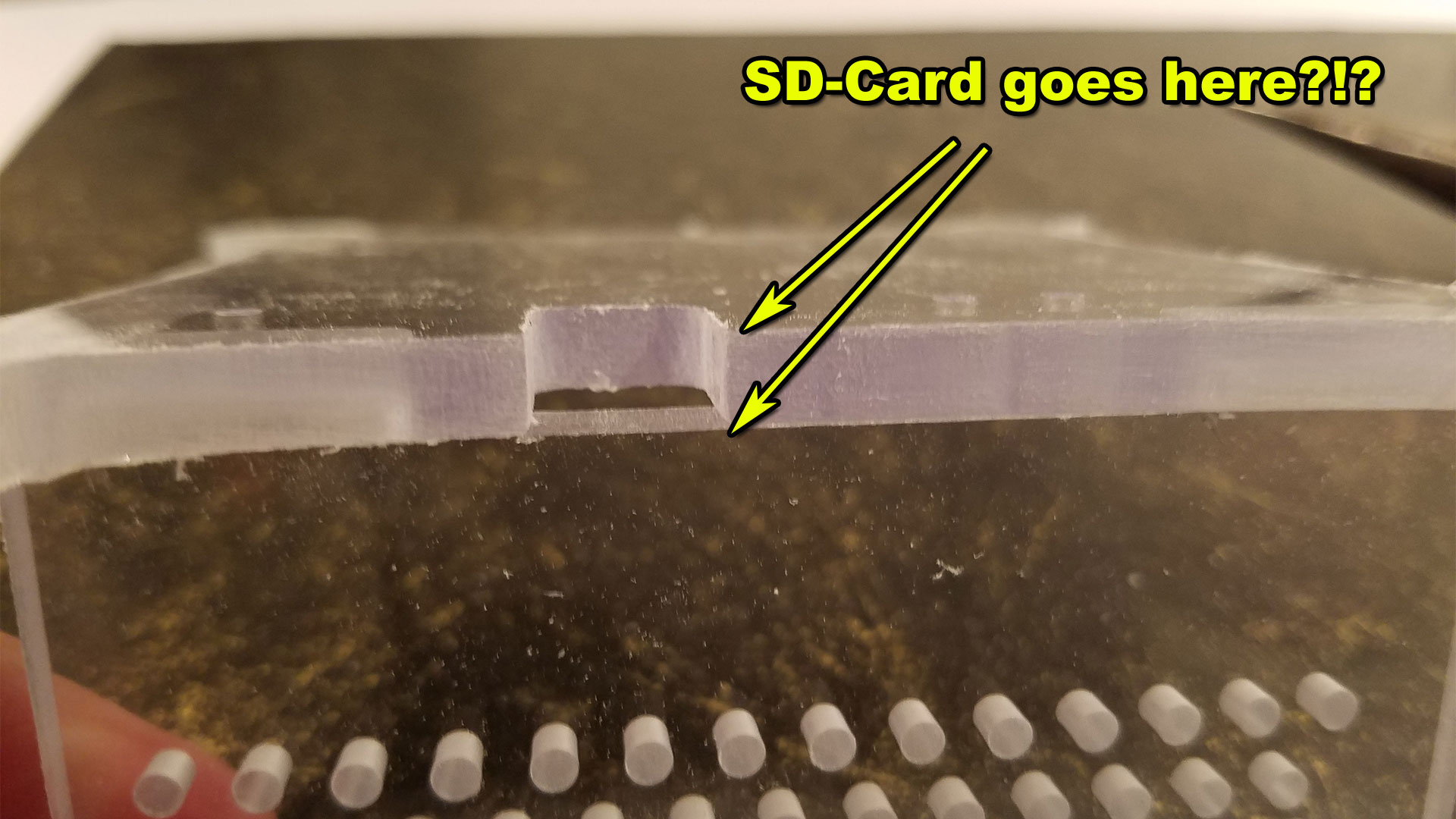 Another design flaw (Which we did correct in the InkScape SVG file) Is that we were working with some super-thick material. As a result, having a slot just below the bottom of the case to access the SD-Card will simply not do! On top of the Raspberry Pi 3 board being elevated 3mm away from the surface. There's no way for the card to easily slide out. Ultimately we had to route out a notch by hand on the wall to match so we can pull the SD-Cards out of my Pi with relative ease.
Why are you telling us your failures?!?
Easy, so you don't do them. If you get the opportunity to take this drawing to a robotic router at some university then you'll know what to look out for. Even failure brings knowledge. If my failures helps at least one person build a better case with a CNC or Robotic Router. Then I have saved that one person a hell of a lot of money on expensive substrates.
The Fit-Test
 The fit-test was not perfect. For starters on my initial design, we inverted the holes for my DC-DC circuits and the 2mm holes could've been a little bigger to give me some play when I threw my fasteners in. With a little bit of rotary tool, action solved that problem. But overall it fits exactly the way I want it to. Everything is behind the engraved marks were the walls shall stand. So far so good on this one!
Electrical assembly.
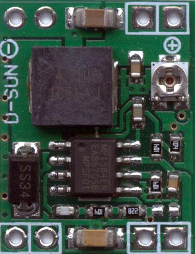
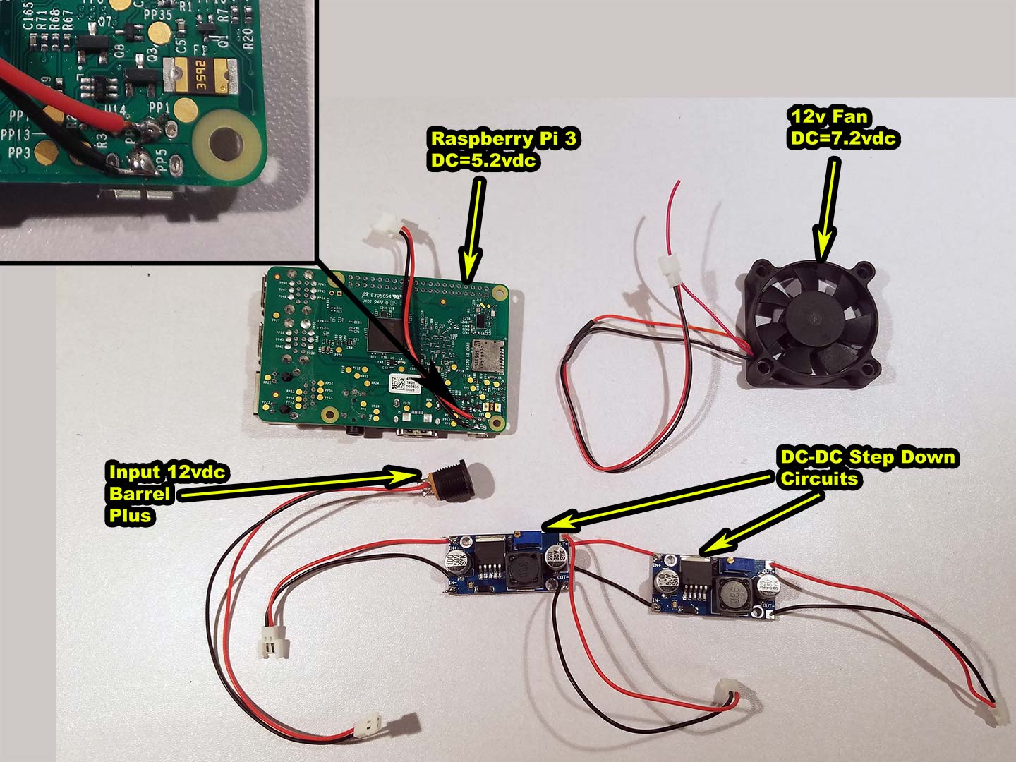 For the wiring of this, we decided to keep it similar to our previous raspberry Pi cases using the traditional 12vdc barrel plug that we tend to find on a lot of power bricks on the market. Where positive polarity is on the pin wire and negative is on the outer barrel. This feeds into two LM2596 DC-DC Step-down circuits which have the capability of delivering up to 3 amps per DC-DC circuit. More then what we need for our Raspberry Pi.
DC-DC Circuit #1
One DC-DC Circuit is set for 7.2 volts for the fan because 12-volt fans even at 40mm in size still make a hell of a lot of noise at full blast. 7.2 volts is just enough where the air is moving good but it's barely making any noise for us. Your settings were vary depending on the fan type you choose for your case.
DC-DC Circuit #2
The other DC-DC Circuit shall go off to the Raspberry Pi case at 5.2 volts. Why this voltage? 5.25 volts is the ceiling limit of the USB Standards. We also set it near the ceiling because as you run your CPU on your Pi at 100 percent and you keep your voltmeter on it you'll find that voltage does drop a little. If it drops below 4.8volts on the Raspberry Pi the B+'s and 2 series would just lock. The 3 series will warn you showing an icon in the upper right-hand corner warning of power failure.
Raspberry Pi direct wiring.
You should also notice we decided to solder two wires onto the back of our Raspberry Pi; With positive going to PP2 and Negative going to PP5. You can plug in your USB charger to your Raspberry Pi and power it on to test these pads yourself.
DC-DC Insanity
 There's a reason why we love DC-DC circuits and that's because when we first got into the Raspberry Pi we had terrible luck keeping it stable. This is because of the overall quality of USB wiring where there was too much resistance along a USB cable the moment you exceed 5volts 1amp. The Raspberry Pi 3 can potentially take above 2 amps of power. USB cables suck as a power delivery method unless you have a battery backup system like cel-phones have. So we soldered some heavier gauge wire to the bottom of the Pi to eliminate that problem. We also didn't go through the GPIO because feeding voltage that way bypasses all protection. We would rather have the power circuits of the Pi do their job.
 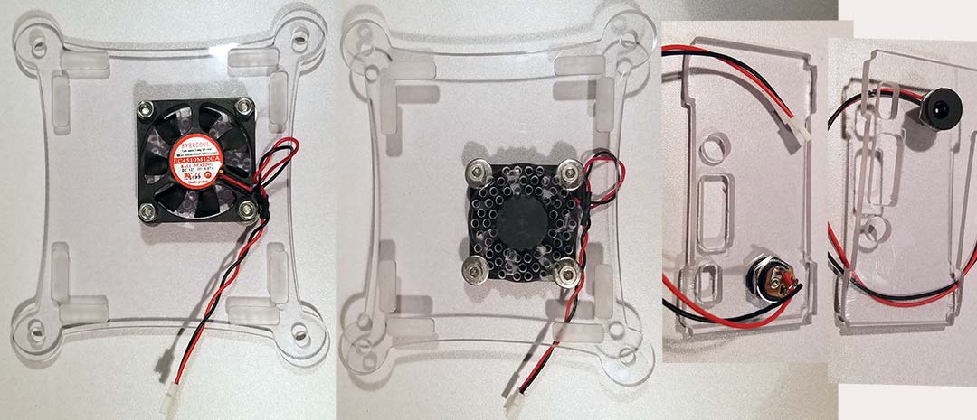 Finally, with all of the main components wired. We wire up the fans. Using a 4mm machine bold and a washer in between the fan and plastics to prevent the blades from touching. Also, my 12vdc jack will come off of a power brick. We used break-away cables throughout the entire process to make it easy to service and also in case we ever have to disconnect the DC-DC circuit and hook the Raspberry Pi up the old-fashioned way (Hooking up a USB charger.)
Second Raspberry Pi 3 case Fit Test.
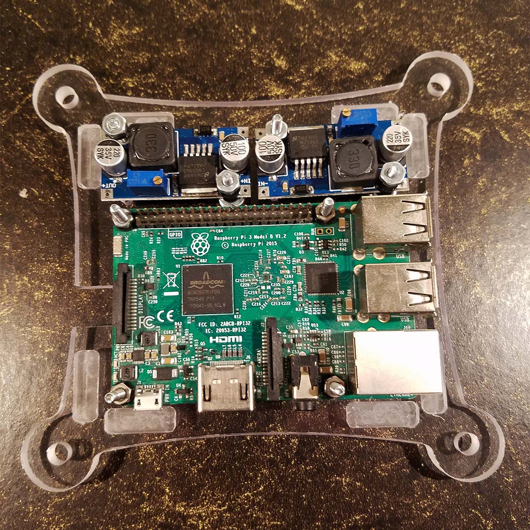
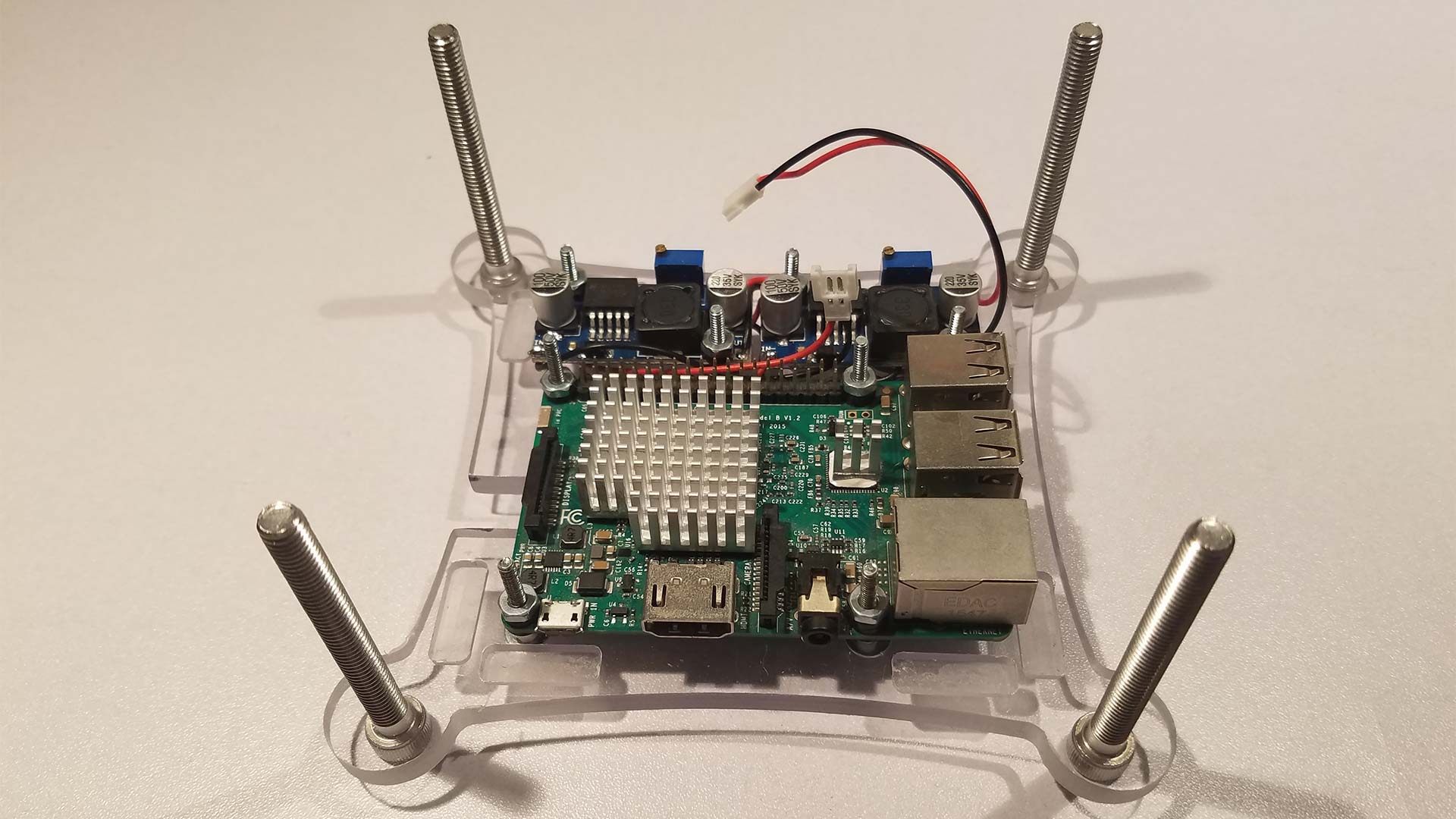 This is the second fittest. This time we made sure our M6x60mm bolts were able to go through the holes nice which they did. Also with the electrical properly wired along the bottom, we were able to bolt the Raspberry Pi down using M2 machine screws and washers. Most importantly, all of the wires are still behind the engraving marks allowing the outer walls of this case to be put on.
Heat-sink mod.
The heat-sink we are using originally came off of a north-bridge chip of an old IBM motherboard. I pulled it off because I never knew when I would need a small heat sink. This Pi is perfect for it. The only thing I had to do was using the carbide bit on my hand rotary tool and a set of heat resistant gloves to hold the heat sink.. cut away a small corner so I do not accidentally ground out my power supply. Then, Using double-sided thermal tape we were able to mount the heat-sink and the Ethernet chip. It's not the largest heat sinks we have seen on a Pi-based product. But not the smallest either! This will help in keeping the Pi cool in an enclosed environment like our Polycarbon case. The scrap we cut off fit on the other chip perfectly. Which is awesome. No waste.
The Finale.
 Well, I have to say this was a hell of a fun project. We got to learn about CNC Routers and what the industry does to make an acrylic case. Despite all of the errors we've had in making one it still looks pretty as hell. I still have to see about finding some PVC tubing in different colors with a 6mm diameter so we can dress up and hide the bolt screws for a more professional finish. But all and all. It was awesome.
Update 09/14/2018 - Adding some dressing.
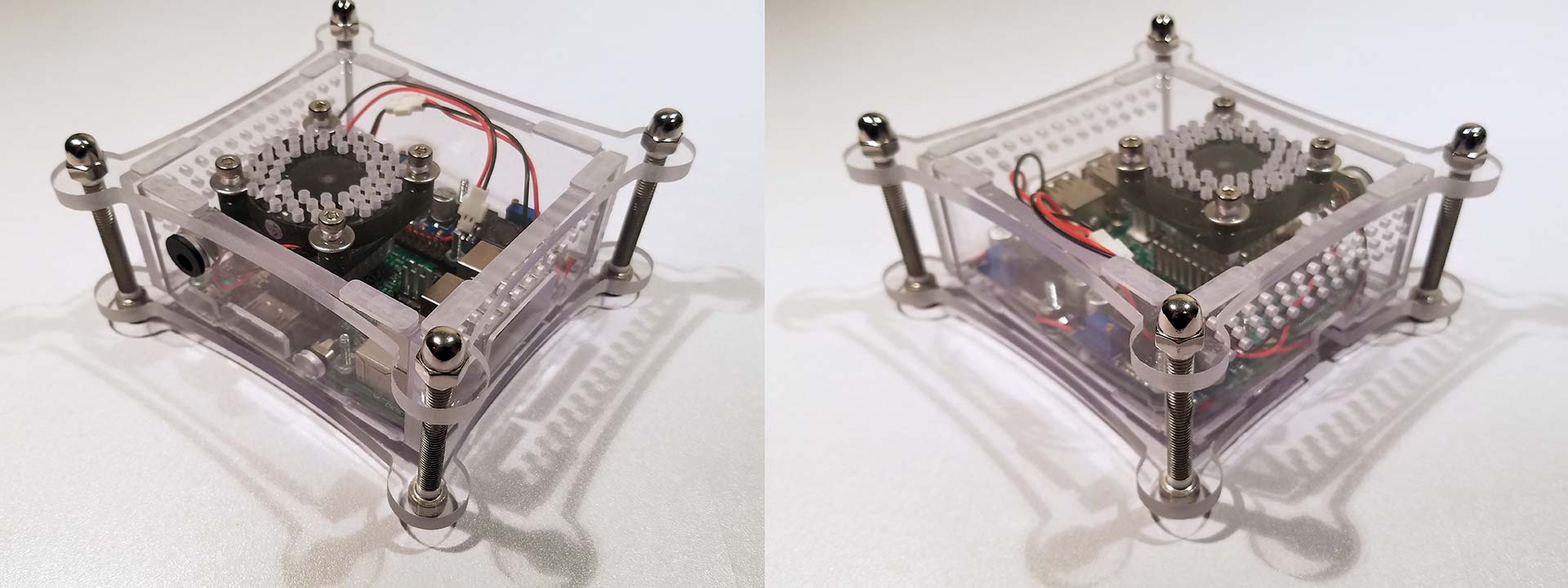
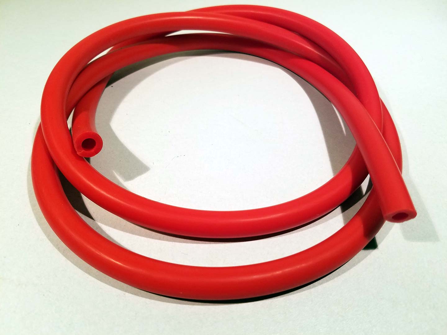 I didn't like how the bare screws looked on the outside corners. So we got some 6mm inner diameter vacuum hoses that are typically used for automotive purposes. It was about a buck a foot online so we got about 6 feet of the stuff for error correction and because we did make a few of these cases. My suggestion to anyone using colored vacuum lines is to use scissors instead of electrical snips. The cut will be cleaner as its soft PVC tubing. And go 4mm more than what you're cutting. That way when you drop your screws down the hose will compress a little. But not so much that it ripples the PVC tubing.
 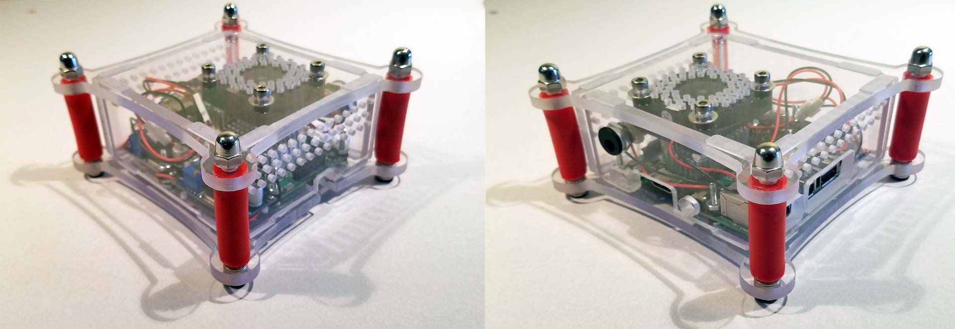 Now it's starting to look like a legit case instead of coming straight out of a Fastenal catalog. Not that we are saying they are bad. If you like the aesthetic then that's awesome. But having a little bit of color in the case accents it well.
Final Thoughts.
Yeah, but does it still run after you soldered and hacked it together?!?! Huh!!?!?
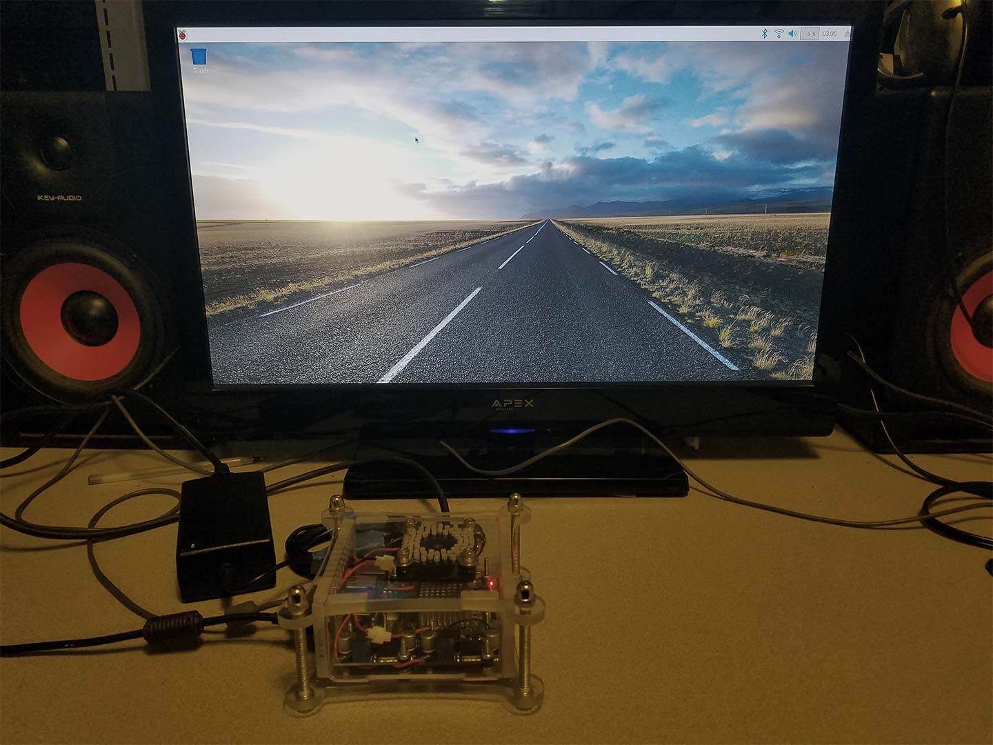
Yeah. It's still working. Wi-Fi is good too. Apologies for the terrible lighting in this picture.
This was a little more work than we expected. But then again If we did cardboard mock-ups first before just jumping right on in with the CNC router we probably could've avoided all of these terrible mistakes. It was a teachable lesson that produced an awesome case which now you too can witness and enjoy as well. Did we outperform a raspberry Pi case made by a Chinese factory? yes and no. Yes, in the respect that we are using higher-grade materials and parts which will last for the lifetime of the raspberry pi. I get to control the power every step of the way, from the 12v brick to the DC-DC controller and so on. No, in the respect that making one of these cases with the fasteners and everything else would probably be around $30+ per unit. About the same cost as the Raspberry Pi itself.
Ultimately, we think that EVERYONE should make their case for a Raspberry Pi. Because it represents your creativity and tells everyone who sees your Pi a little bit about you. This is why we published our dimensional layouts in case someone else wants to grab it and carve their path with it. You are welcome to ask any question except what CNC Router we used. Nanners is very protective of that and don't want anyone else in the elderly home cutting fruitcake as clean as she does. Hence I will have to trash any comments about the technical specifications of the CNC Router we used. Nor will we answer questions about Nanners as a subversive way to find out about the router. We hope you understand. Those people in the elderly home are vicious!
Until then, that's what server said.
+++END OF LINE.